Method and apparatus for operating gas turbine engines

a gas turbine engine and gas turbine technology, applied in the direction of mechanical equipment, machines/engines, sustainable transportation, etc., can solve the problems of increasing the weight increasing the cost of the gas turbine engine assembly, and increasing etc., to facilitate the reduction of the operating temperature of the lubricating fluid, the effect of the outer wall

Active Publication Date: 2010-09-23
GENERAL ELECTRIC CO
View PDF25 Cites 52 Cited by
  • Summary
  • Abstract
  • Description
  • Claims
  • Application Information

AI Technical Summary

Benefits of technology

[0006]In another aspect, a splitter for a gas turbine engine is provided. The splitter includes a radially inner wall, a radially outer wall connected to the radially inner wall at a leading edge, an inner support structure coupled between the inner and outer walls such that a flowpath is defined between at least a portion of the inner support structure and the inner and outer walls, and a cooling circuit extending through a portion of the inner support structure for circulating lubrication fluid through the flowpath such that as a temperature of the lubrication oil is reduced and a temperature of at least a portion of the inner and outer walls is increased.
[0007]In a further aspect, a gas turbine engine assembly is provided. The gas turbine engine assembly includes a fan assembly, a booster downstream from the fan assembly, and a splitter circumscribing the booster. The splitter includes a radially inner wall, a radially outer wall connected to the radially inner wall at a leading edge, an inner support structure coupled between the inner and outer walls such that a flowpath is defined between at least a portion of the inner support structure and the inner and outer walls, and a cooling circuit extending through a portion of the inner support structure for circulating lubrication fluid through the flowpath such that as a temperature of the lubrication oil is reduced and a temperature of at least a portion of the inner and outer walls is increased.

Problems solved by technology

During engine operation, the temperature of the lubricating fluid increases undesirably.
Accordingly, reducing the operating temperature of the lubrication fluid utilizing a known heat exchanger may increase the cost of the gas turbine engine assembly and may also increase the weight of the gas turbine engine assembly thus reducing overall engine efficiency.

Method used


Image

  • Method and apparatus for operating gas turbine engines
  • Method and apparatus for operating gas turbine engines
  • Method and apparatus for operating gas turbine engines

Examples


Embodiment Construction

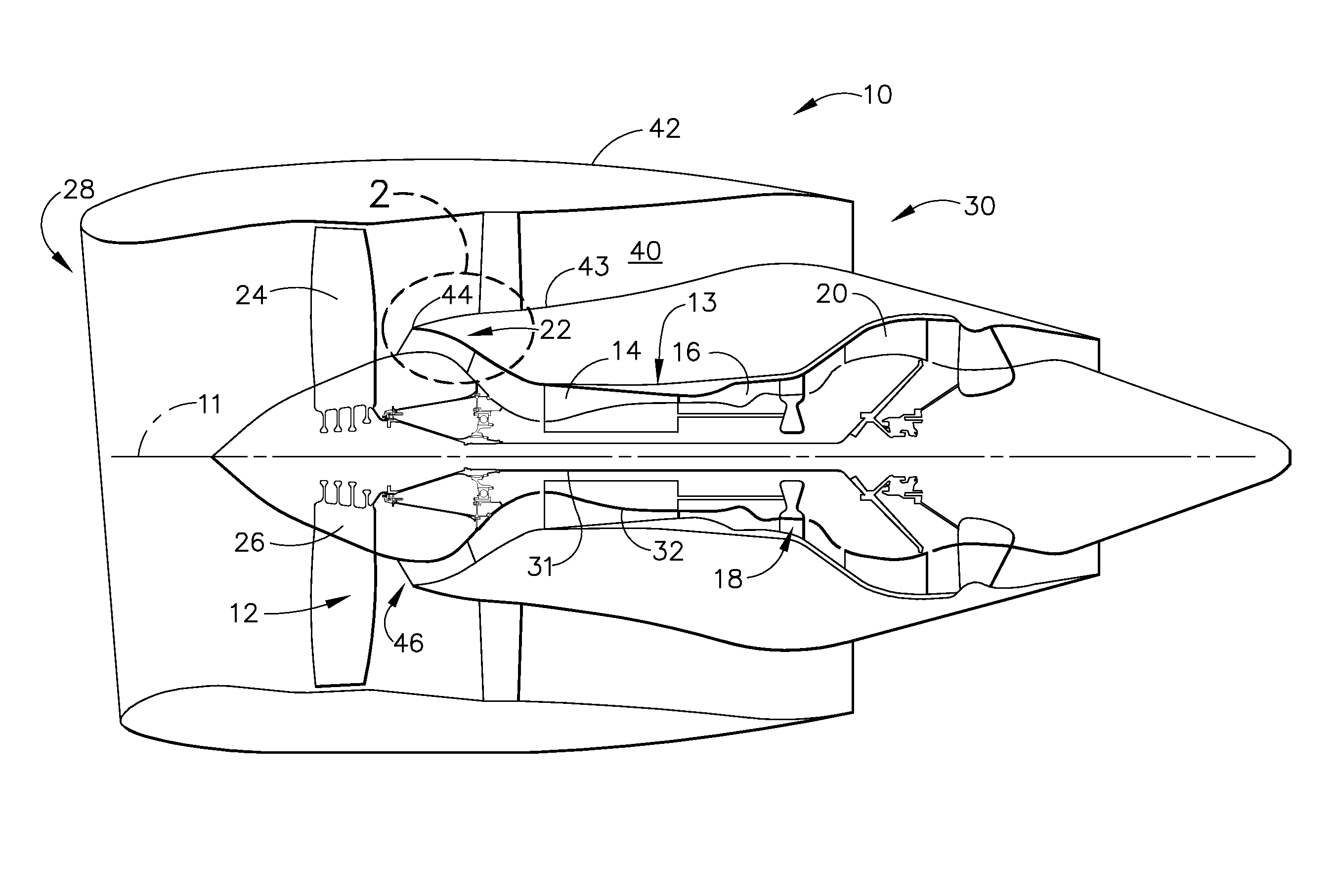
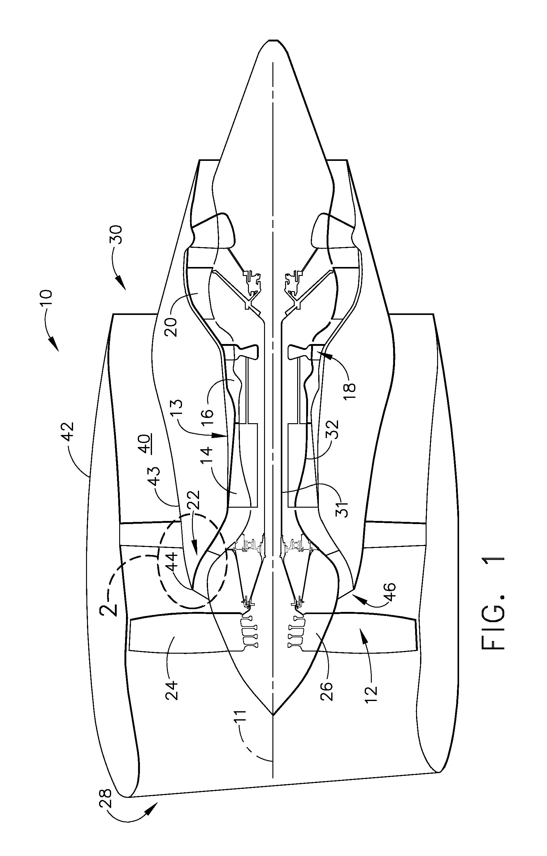
[0015]FIG. 1 is a schematic illustration of an exemplary gas turbine engine assembly 10 having a longitudinal axis 11. Gas turbine engine assembly 10 includes a fan assembly 12, and a core gas turbine engine 13 that includes a high pressure compressor 14, a combustor 16, and a high pressure turbine 18. In the exemplary embodiment, gas turbine engine assembly 10 also includes a low pressure turbine 20 and a multi-stage booster compressor 22 also referred to as an intermediate pressure compressor.

[0016]Fan assembly 12 includes an array of fan blades 24 extending radially outward from a rotor disk 26. Engine 10 has an intake side 28 and an exhaust side 30. In the exemplary embodiment, gas turbine engine 10 is a GE90 gas turbine engine that is available from General Electric Company, Cincinnati, Ohio. Fan assembly 12, booster 22, and low-pressure turbine 20 are coupled together by a first rotor shaft 31, and compressor 14 and high-pressure turbine 18 are coupled together by a second rot...


PUM

PropertyMeasurementUnit
temperatureaaaaaaaaaa
swirl angleaaaaaaaaaa
support structureaaaaaaaaaa

Abstract

A method for assembling a turbine engine to facilitate reducing an operating temperature of a lubrication fluid during engine operation, the gas turbine engine including a fan assembly, a booster downstream from the fan assembly, and a splitter circumscribing the booster. The method includes coupling a radially inner wall and a radially outer wall at a leading edge to form a splitter body, and coupling an inner support structure within the splitter body such that a cooling circuit is defined between at least a portion of the inner support structure and the inner and outer walls, said cooling circuit configured to circulate lubrication fluid therethrough such that as a temperature of the lubrication fluid is reduced and a temperature of at least a portion of the inner and outer walls is increased.

Description

BACKGROUND OF THE INVENTION[0001]This invention relates generally to gas turbine engines, and more particularly, to gas turbine engines and methods of assembling the same.[0002]Gas turbine engines typically include low and high pressure compressors, a combustor, and at least one turbine. The compressors compress air which is channeled to the combustor where it is mixed with fuel. The mixture is then ignited for generating hot combustion gases. The combustion gases are channeled to the turbine(s) which extracts energy from the combustion gases for powering the compressor(s), as well as producing useful work to propel an aircraft in flight or to power a load, such as an electrical generator.[0003]During engine operation, a lubrication system is used to lubricate gas turbine engine components. For example, the lubrication system is configured to channel lubrication fluid to various bearing assemblies within the gas turbine engine. During engine operation, the temperature of the lubrica...

Claims


Application Information

Patent Timeline
Patent Type & Authority Applications(United States)
IPC IPC(8): F02C7/12B23P17/00
CPCF01D25/14F02C7/14F02K3/06Y10T29/49229Y02T50/675F01M5/005F16N29/02F02K3/115F02C7/06Y02T50/60
Inventor SCHILLING, JAN CHRISTOPHER
Owner GENERAL ELECTRIC CO
Why Eureka
Try Eureka