
Method and system to generate steam in a digester plant of a chemical pulp mill

a technology of chemical pulp mill and digester plant, which is applied in the direction of papermaking, pretreatment with water/steam, and finely divided material pretreatment, etc., can solve the problems of unsatisfactory, volatile compounds in steam produced, and the need for further improvement of the energy efficiency of the chemical pulp mill, so as to improve the energy efficiency of the pulp mill

Active Publication Date: 2010-09-23
ANDRITZ INC
View PDF3 Cites 17 Cited by
  • Summary
  • Abstract
  • Description
  • Claims
  • Application Information

AI Technical Summary

Benefits of technology

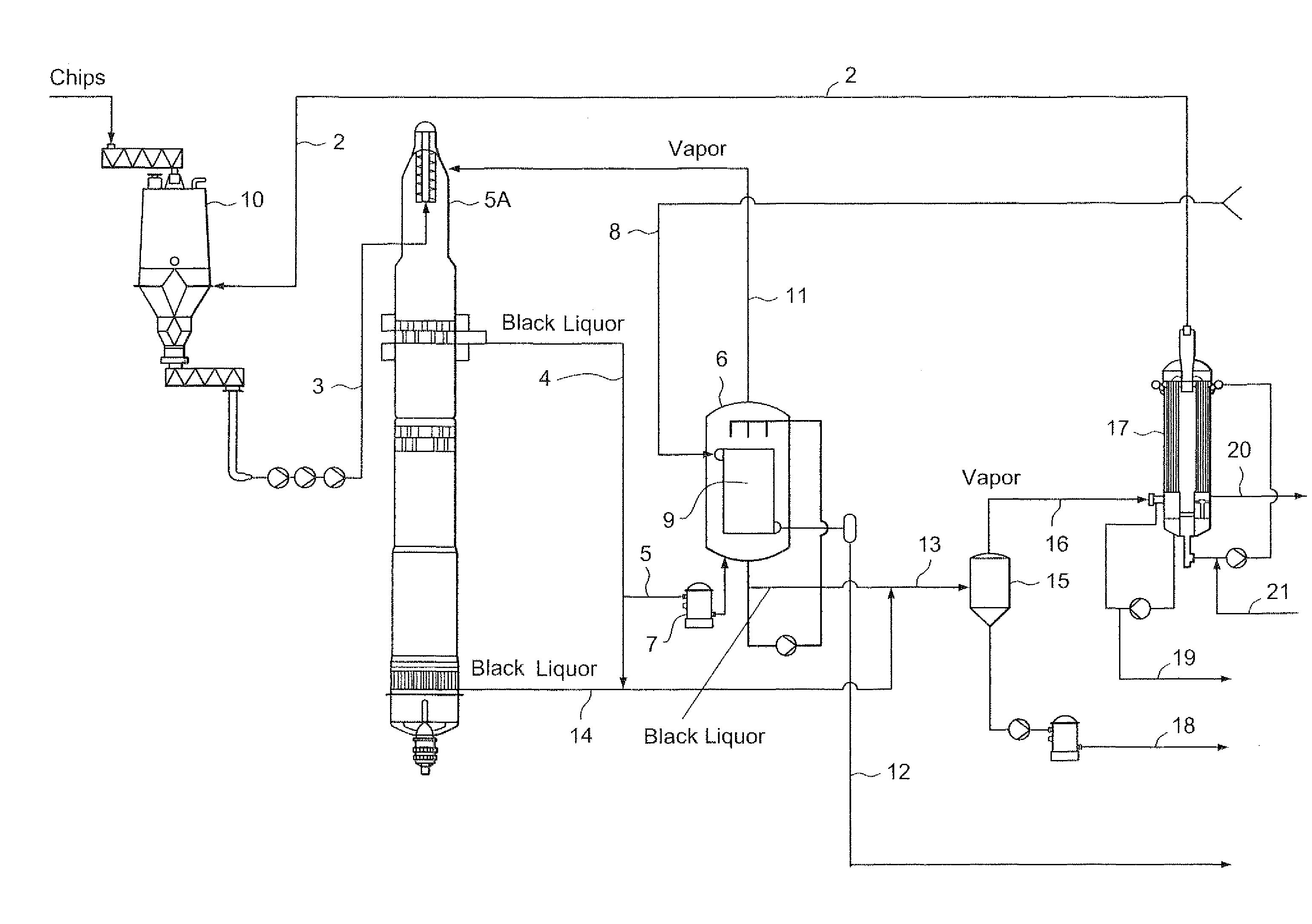
[0015]A method and system have been invented for the production of clean steam for steam pre-treatment of wood chips by utilizing the heat of black liquor and for the production of steam from black liquor for heating fibrous material in a digester. Steam and vapor is generated from black liquor so that the treated black liquor has better properties as regards the further treatment in the recovery area of the pulp mill. Further, the energy economy of the whole pulp mill can be improved with the method and system disclosed herein.

Problems solved by technology

The above flashing process, though it has been successfully employed in conventional continuous digesters, has the drawback that the steam produced contains volatile compounds, including sulfur compounds, which are undesirable in the presteaming of wood chips.
However, this collection and treatment system becomes particularly significant when the steam used contains volatile compounds, including sulfur compounds, which have undesirable environmental impact, including noxious odor.
Due to the cost of energy, any further improvement to the energy efficiency of the chemical pulp mill is needed.

Method used


Image

  • Method and system to generate steam in a digester plant of a chemical pulp mill
  • Method and system to generate steam in a digester plant of a chemical pulp mill

Examples


Embodiment Construction

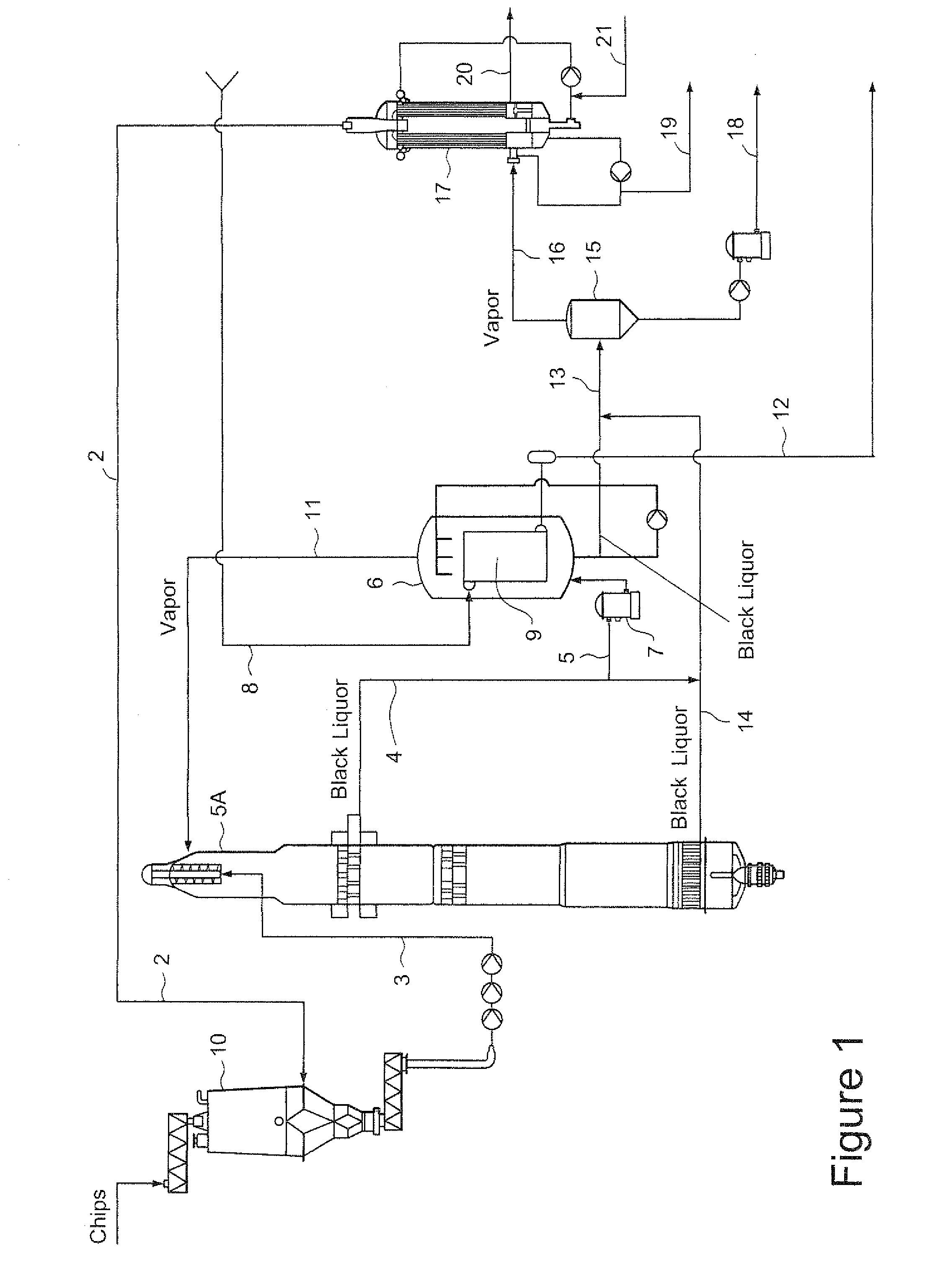
[0031]FIG. 1 illustrates a system for generating steam in a digester 5a plant and for treating black liquor so that the heat efficiency of the cooking process is improved. The fiberline system comprises a chip bin 10 where steaming of wood chips or other cellulose material occurs with steam from line 2 (a line is a conduit such as a pipe), liquid is added to form a slurry, followed by pressurization of the slurry (this section is also referred to as the feed system) followed by a continuous digester 5a (this section is also referred to as the cooking system). Before the digester 5a, the slurry may be optionally fed to and treated in a treatment vessel or vessels (could be an impregnation vessel, a pre-hydrolysis process or other vessels, not shown). The slurry of chips and cooking liquid is fed via line 3 to the top of the digester 5a Only those components that are important for the invention are shown in the drawing, and other types of chips steaming or feeding or digester 5a circu...


PUM

PropertyMeasurementUnit
Temperatureaaaaaaaaaa
Pressureaaaaaaaaaa
Contentaaaaaaaaaa

Abstract

A method for generating steam in a digester plant of a chemical pulp mill including: producing black liquor in the digester plant, extracting a first stream of black liquor from the digester; generating vapor by evaporating the first stream of black liquor by heating the first stream with fresh steam; heating fibrous material in the digester with the generated vapor from the evaporated first stream of black liquor; extracting a second stream of black liquor from the digester; flashing the second stream of black liquor to generate flashed black liquor and flashed black liquor vapor; introducing the flashed black liquor vapor to at least one heat exchanger to indirectly heat a clean evaporable liquid to produce clean steam from the clean evaporable liquid; and steaming, with the clean steam produced in the at least one heat ex-changer, cellulosic feed material before feeding the cellulosic feed material to the digester plant.

Description

CROSS RELATED APPLICATION[0001]This application relates to and claims priority to Finnish Patent Application No. 20090039 filed on Feb. 9, 2009, the entirety of which is incorporated by reference.BACKGROUND OF INVENTION[0002]The present invention relates to a method for generating steam from a black liquor in a digester plant of a chemical pulp mill.[0003]Conventionally, fiberline systems have a chip bin where steaming of wood chips or other cellulose material occurs, liquid is added to form a slurry, followed by pressurization of the slurry (this section is also referred to as the feed system), fed to a treatment vessel or vessels (could be an impregnation vessel, a pre-hydrolysis process or other vessels), followed by a digester (this section is also referred to as the cooking system). Currently, at least one black liquor stream (typically at a temperature of 110-150° C.) is withdrawn from the cooking system. The extracted black liquor stream or streams are used as a source of hea...

Claims


Application Information

Patent Timeline
IPC IPC(8): D21C1/02D21C7/00
CPCD21C11/06D21C7/00D21C1/02D21C3/22
Inventor TIKKA, PETRIKAILA, JARMO
Owner ANDRITZ INC
Learn More