Vehicle mounted converter

a converter and vehicle technology, applied in hybrid vehicles, electric devices, electrochemical generators, etc., can solve problems such as increasing the size of the system

Inactive Publication Date: 2010-09-23
TOYOTA CENT RES & DEV LAB INC
View PDF3 Cites 44 Cited by
  • Summary
  • Abstract
  • Description
  • Claims
  • Application Information

AI Technical Summary

Problems solved by technology

However, when mounting an external charging device in addition to a battery and booster converter to a vehicle, there was a problem with the increase in size of the system.

Method used


Image

  • Vehicle mounted converter
  • Vehicle mounted converter
  • Vehicle mounted converter

Examples


first embodiment

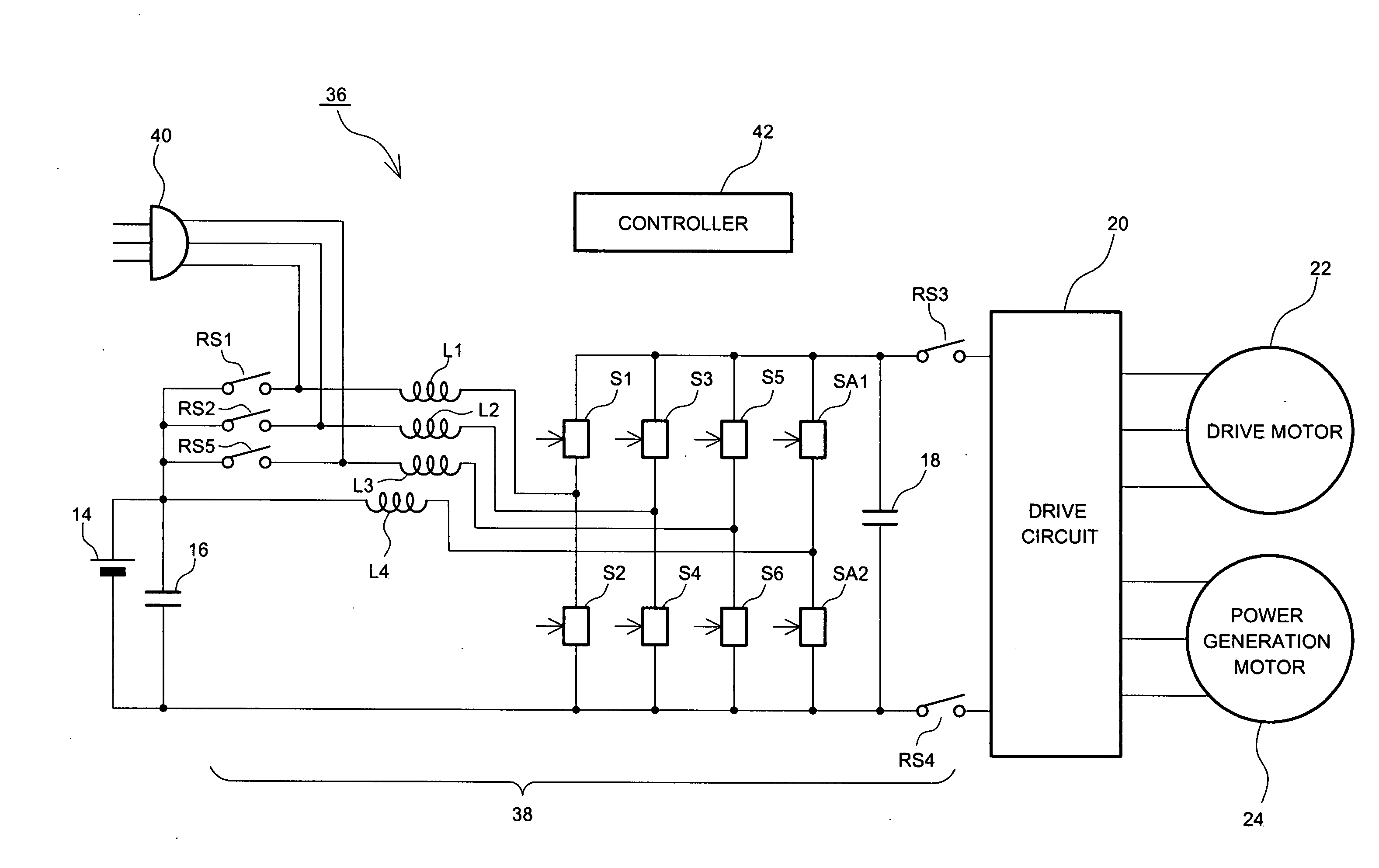
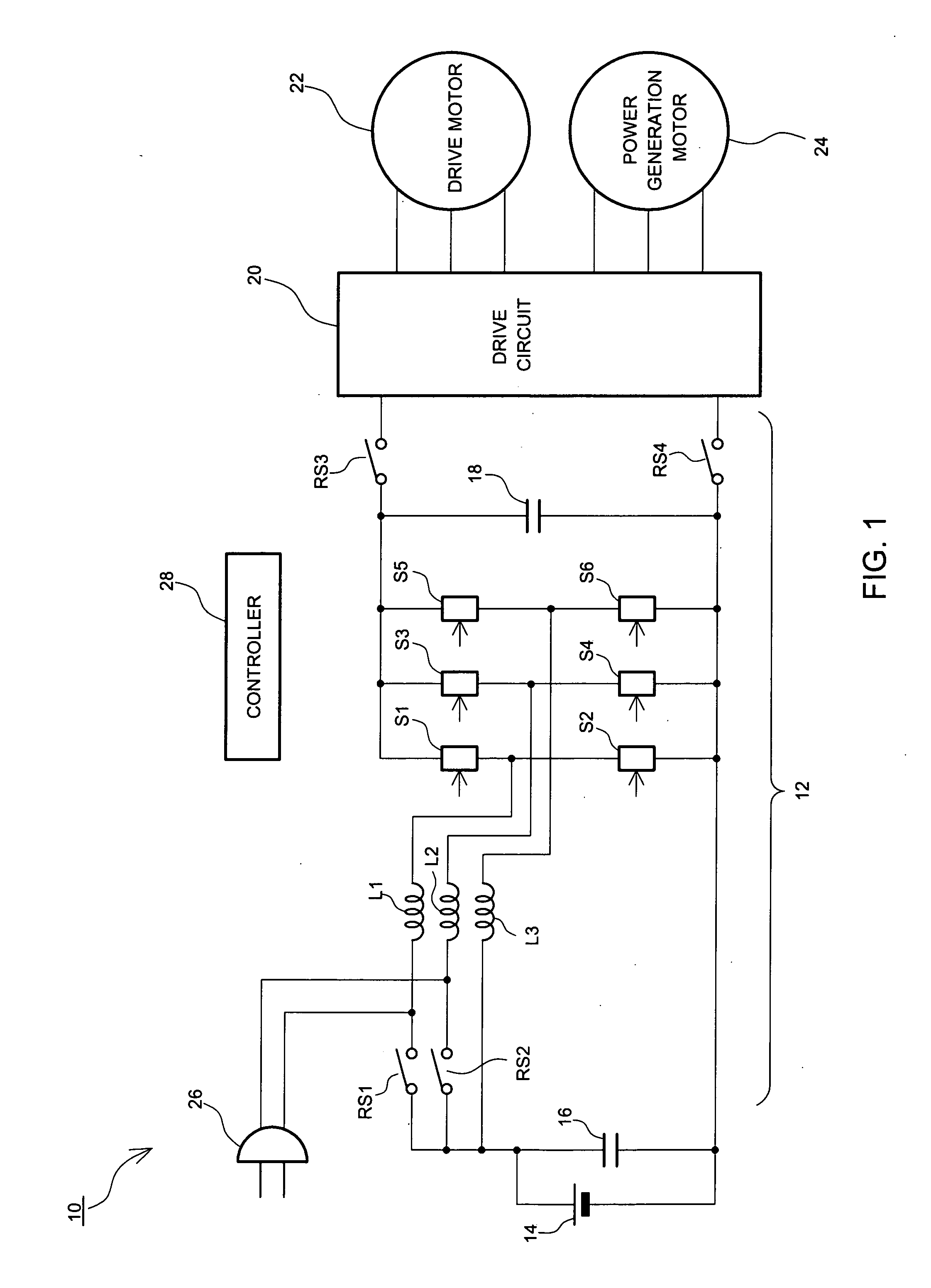
[0024]FIG. 1 shows a configuration of a hybrid vehicle drive system 10 relating to the present invention. The hybrid vehicle drive system 10 includes a switching three-phase multiphase converter 12. The switching three-phase multiphase converter 12 charges a battery 14 for vehicle drive power supply on the basis of power obtained from an external power supply device, such as a commercial power supply, or boosts and outputs the output voltage of the battery 14 to a drive circuit 20. Furthermore, the drive circuit 20, a drive motor 22, and a power generation motor 24 are provided, where the drive circuit 20 performs direct current to alternating current conversion and transfers power between the switching three-phase multiphase converter 12 and the drive motor 22 as well as the power generation motor 24.

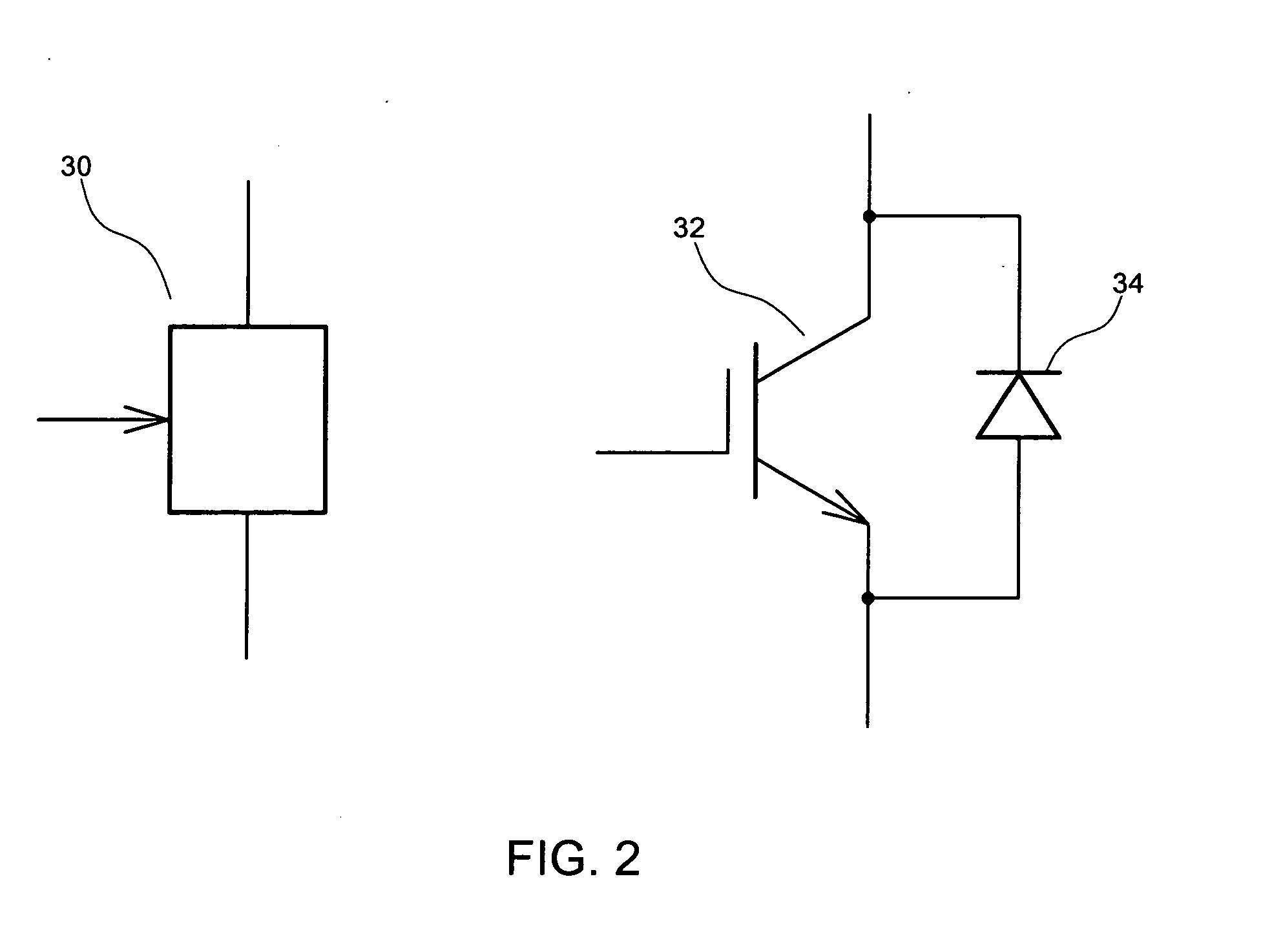
[0025]The switching three-phase multiphase converter 12 has a configuration where inductors are connected to connection nodes between the switching devices connected at the top and bot...

second embodiment

[0068]FIG. 6 shows a configuration of a hybrid vehicle drive system 44 relating to the present invention. The hybrid vehicle drive system 44 includes a switching six-phase multiphase converter 46. The switching six-phase multiphase converter 46 charges the battery 14 based on the electric power obtained from the external power supply device, such as a commercial power supply, or boosts and outputs the output voltage of the battery 14 to the drive circuit 20. The same reference numerals have been applied to parts identical to those shown in FIG. 1 and the descriptions thereof will be omitted.

[0069]The switching six-phase multiphase converter 46 has a configuration where inductors are connected to the connection nodes between the switching devices connected at the top and bottom. The switching six-phase multiphase converter 46 operates in either a boost mode for boosting the output voltage of the battery 14 or an external charging mode for charging the battery 14 on the basis of power...


PUM


Abstract

An object is to miniaturize device size in a vehicle mounted converter. The vehicle mounted converter includes a plurality of inductors, a switching unit for switching current path, an external power acquisition unit for acquiring alternating current power from a power generation source provided separately from the mounted vehicle, and a switching means for switching a circuit connection state to a connection state of either a boost connection state for connecting one end of the inductors to a path to a battery for vehicle drive power supply and connecting the switching unit to the other end of the inductors, or a charging connection state for connecting one end of one of the plurality of inductors to the path to the battery, disconnecting one end of the remaining inductors from the path to the battery and connecting to the external power acquisition unit, and connecting the other end of the inductors to the switching unit.

Description

PRIORITY INFORMATION[0001]This application claims priority to Japanese Patent Application No. 2009-066682 filed on Mar. 18, 2009, which is incorporated herein by reference in its entirety.BACKGROUND OF THE INVENTION[0002]1. Field of the Invention[0003]The present invention relates to a vehicle mounted converter including a plurality of inductors for performing switching of currents flowing to the inductors.[0004]2. Description of Related Art[0005]Hybrid automobiles and electric automobiles traveling by the driving force of a motor are widely used. These motor driven vehicles include a battery for supplying the driving power to the motor and a booster converter for boosting a battery voltage and outputting the boosted voltage to a motor drive circuit.[0006]The booster converter includes inductors and switching circuits for switching currents flowing to the inductors. The inductors generate an induced electromotive force by switching of the currents. The booster converter outputs to t...

Claims


Application Information

Patent Timeline
Patent Type & Authority Applications(United States)
IPC IPC(8): B60L1/00
CPCB60L11/123Y02T90/14B60L11/1811B60L11/1812B60L11/1814B60L11/1816B60L15/007H01M10/46H02M1/10H02M3/1584Y02T10/6217Y02T10/7005Y02T10/7077Y02T90/127B60L11/1803Y02T10/7072B60L1/006B60L2220/54Y04S10/126B60L53/14B60L53/16B60L53/22B60L50/61B60L50/51B60L53/20B60L53/24B60L55/00Y02E60/00Y02T10/62Y02T10/64Y02T10/70Y02E60/10Y02T90/12Y02T90/16
Inventor FUMA, HIROOUMENO, TAKAJIMANABE, KOTA
Owner TOYOTA CENT RES & DEV LAB INC
Why Eureka
Try Eureka