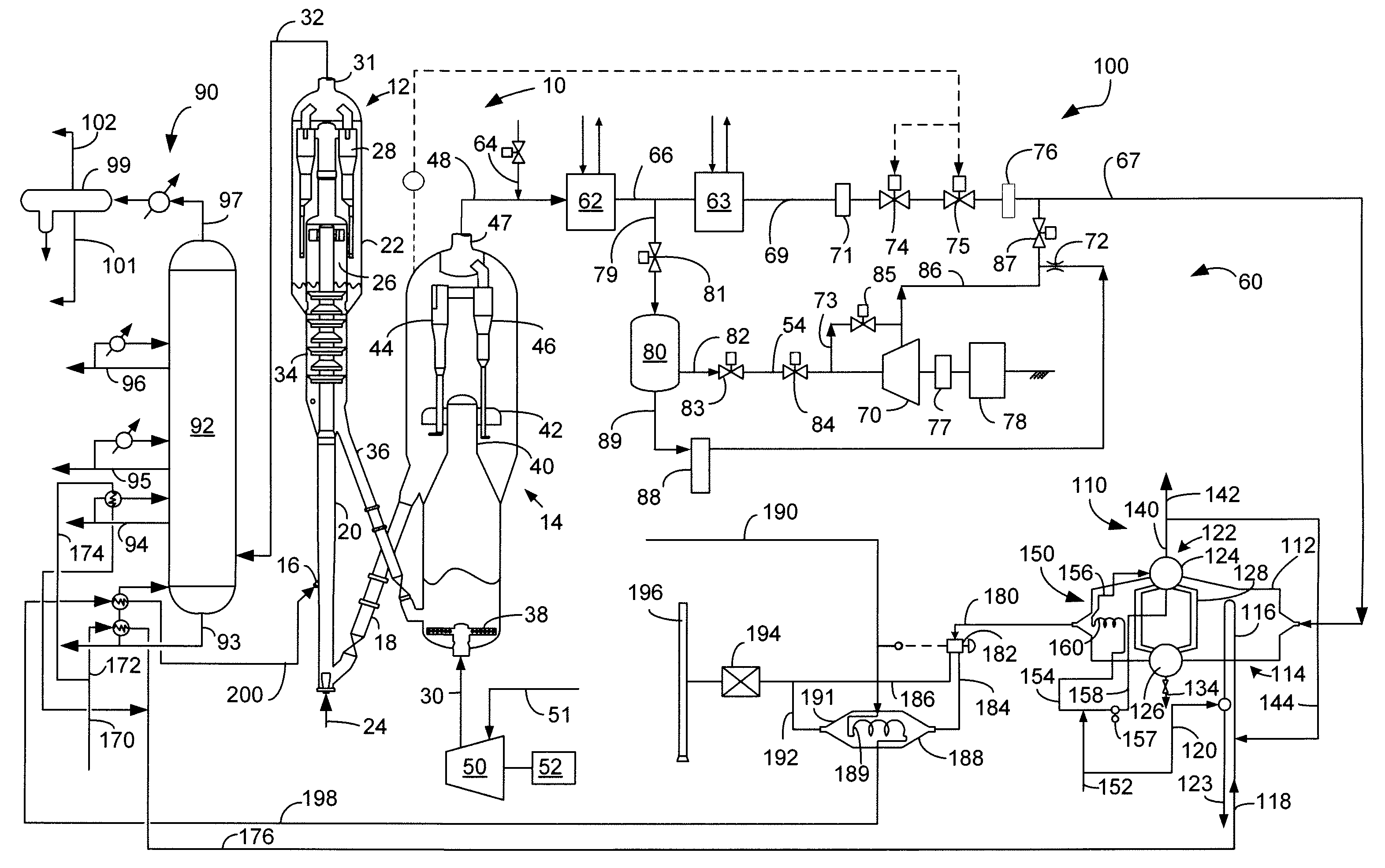
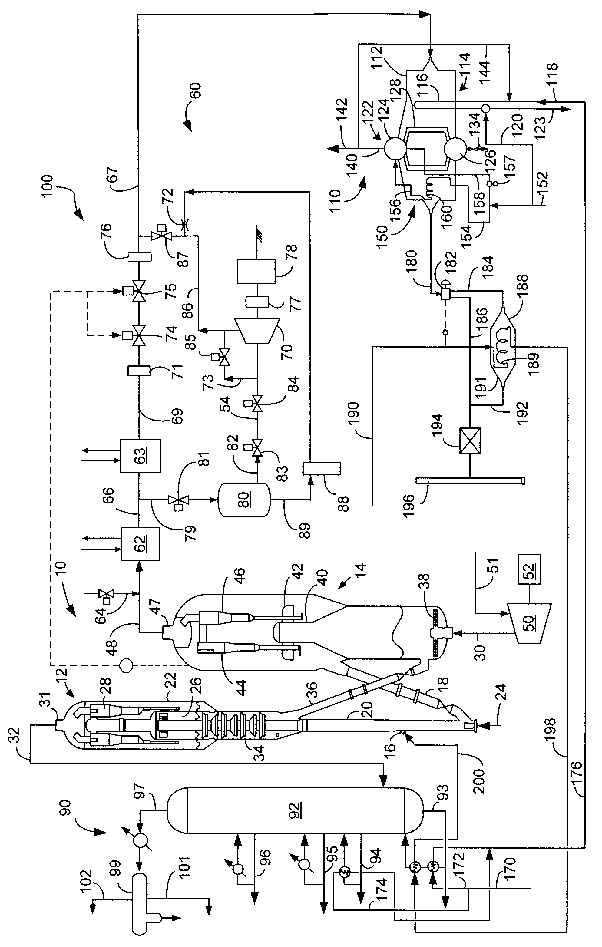
Apparatus for Feed Preheating with Flue Gas Cooler
a technology of flue gas cooler and feed, which is applied in the direction of lighting and heating apparatus, furnaces, physical/chemical process catalysts, etc., can solve the problem of limited flue gas discharge temperature, and achieve the effect of less carbon dioxide, excellent material, and safe avoiding the risk of sulfuric acid condensation
- Summary
- Abstract
- Description
- Claims
- Application Information
AI Technical Summary
Benefits of technology
Problems solved by technology
Method used
Image

Examples
example
[0035]We prophetically calculated the cost savings associated with heat exchanging flue gas with hydrocarbon feed in and FCC unit which is presented in the Table.
Cooling FlueGas in FlueGas Cooler andBaseFeed PreheatCaseExchangerIncrementHP Steam from Flue Gas, Mt / hr74.2066.60−7.60HP Steam from Slurry Oil, Mt / hr74.9991.4116.42HP Steam from HCO, Mt / hr0.0027.1127.11Total HP Steam, Mt / hr149.20185.1235.92Benefit; MM$ / yr44.254.910.6
[0036]By heat exchanging flue gas with hydrocarbon feed, more of the heat in heavy FCC product pump around streams is available for HP steam generation. Almost 36 metric tons per hour more of high pressure steam is made than if the slurry oil pump around is used for all of the feed preheating, resulting in incremental benefits of over ten million dollars per year.
PUM
| Property | Measurement | Unit |
|---|---|---|
| temperatures | aaaaa | aaaaa |
| pressure | aaaaa | aaaaa |
| pressure | aaaaa | aaaaa |
Abstract
Description
Claims
Application Information
 - R&D
- Intellectual Property
- Life Sciences
- Materials
- Tech Scout
- Unparalleled Data Quality
- Higher Quality Content
- 60% Fewer Hallucinations
Browse by: Latest US Patents, China's latest patents, Technical Efficacy Thesaurus, Application Domain, Technology Topic, Popular Technical Reports.
© 2025 PatSnap. All rights reserved.Legal|Privacy policy|Modern Slavery Act Transparency Statement|Sitemap|About US| Contact US: help@patsnap.com