Composite Manufacturing Method

a manufacturing method and composite technology, applied in the direction of lamination, paper/cardboard containers, containers, etc., can solve the problem of additional costs in the final assembly

Inactive Publication Date: 2010-09-23
AIRBUS OPERATIONS LTD
View PDF7 Cites 43 Cited by
  • Summary
  • Abstract
  • Description
  • Claims
  • Application Information

AI Technical Summary

Benefits of technology

[0011]wherein the movement of the compaction tool(s) causes the first and second mandrels to move towards the stiffener along inclined paths so as to compact the stiffener between the mandrels.

Problems solved by technology

Since the thickness tolerance of the components is relatively poor this leads to additional costs in the final assembly where the resulting gaps and / or mismatches between skins, ribs and spars must be filled or adjusted with a suitable method to maintain the aerodynamic tolerance of the whole torque box.

Method used


Image

  • Composite Manufacturing Method
  • Composite Manufacturing Method
  • Composite Manufacturing Method

Examples


Embodiment Construction

)

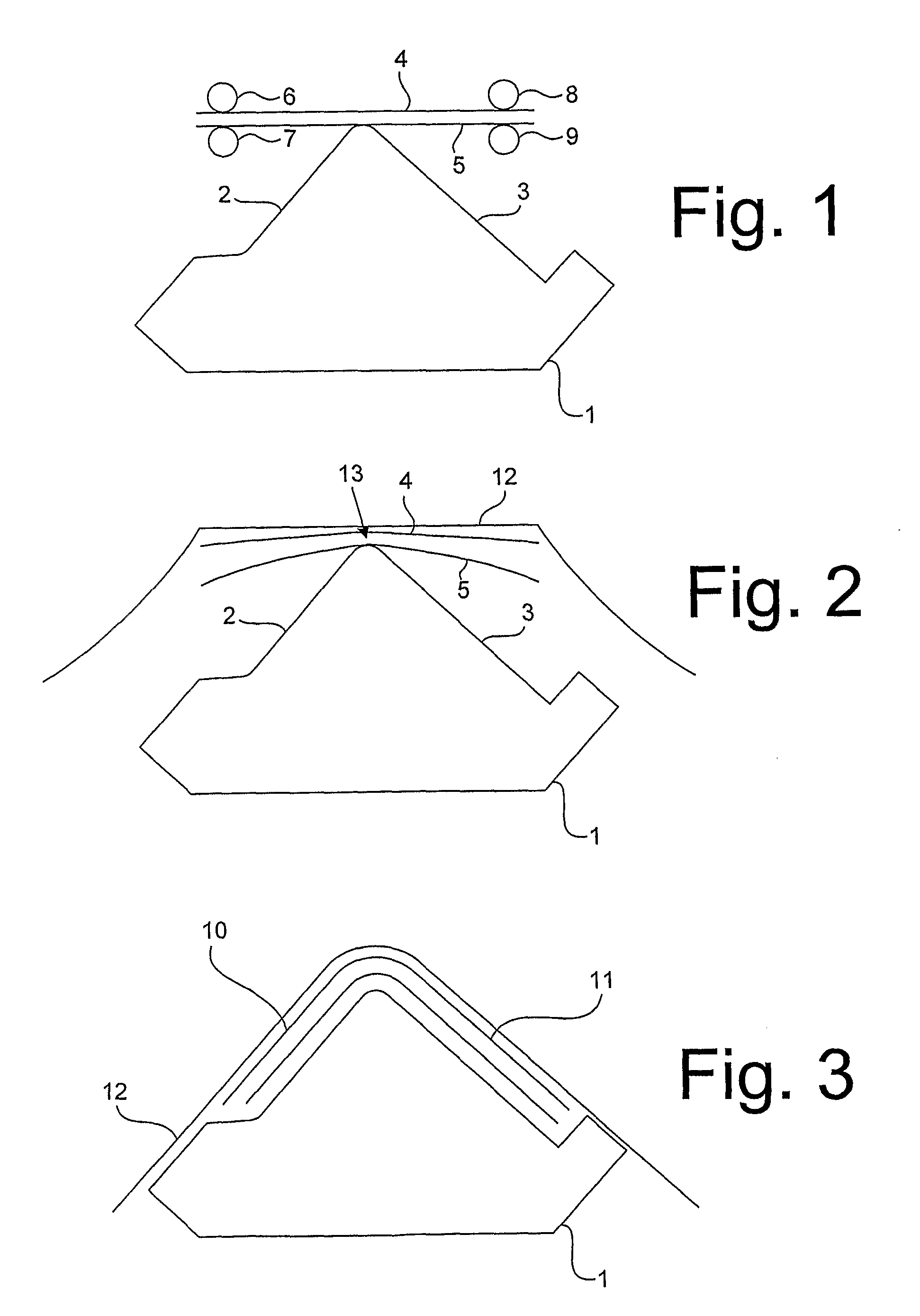
[0054]FIGS. 1-3 show a method of forming an L-shaped stringer preform. In a first step, a stack of prepregs is mounted in a “picture frame” support assembly. In FIG. 1 the stack of prepregs is shown as two plies 4,5 for illustrative purposes, but in general it will appreciated that any number of plies can be used. Each ply comprises an array of uniaxial fibres impregnated with resin. The fibres may be formed of any suitable material such as carbon, glass or aramid and boron. The fibres in adjacent plies run at different angles: for instance the fibres in one ply may run at 0° to the stringer axis, fibres in the next ply may run at may run at 45° to the stringer axis, and fibres in the next ply may run at 135° to the stringer axis (the stringer axis being the axis transverse to the section of FIGS. 1-3).

[0055]The picture frame support assembly comprises a set of spring-loaded rollers arranged around the periphery of the stack. FIG. 1 is a cross-sectional view through the stack so on...


PUM

PropertyMeasurementUnit
anglesaaaaaaaaaa
anglesaaaaaaaaaa
temperatureaaaaaaaaaa

Abstract

A method of manufacturing a panel, the panel comprising a composite skin and at least one composite stiffener, the method comprising: positioning first and second mandrels on opposite sides of the stiffener; positioning first and second compaction tools on opposite sides of the skin; and compacting the skin between the first and second compaction tools by moving one or both of the compaction tools, wherein the movement of the compaction tool(s) causes the first and second mandrels to move towards the stiffener along inclined paths so as to compact the stiffener between the mandrels.

Description

FIELD OF THE INVENTION[0001]The present invention relates to a method and associated apparatus for manufacturing a composite laminate panel and manufacturing a composite laminate. The composite component is typically, although not exclusively, intended to form part of an aircraft.BACKGROUND OF THE INVENTION[0002]The wing or empennage structure of a modem airliner is typically a stiffened skin construction. Together with spars and ribs, the skin forms a torque box which will resist external loads.[0003]In the case of a fuselage, the curved stiffened skin panels together with fuselage frames form the stiffened shell. Traditionally these skins are made from aluminium alloys, but as aircraft performance is becoming more and more important, composite skin panels are becoming more and more popular in aircraft primary structure construction.[0004]Stiffened composite panels in primary structures may be used in horizontal tail plane, vertical tail plane and / or centre wing box construction. T...

Claims


Application Information

Patent Timeline
Patent Type & Authority Applications(United States)
IPC IPC(8): B32B1/00B29C65/02B32B38/10B32B37/00B29C65/78B29D99/00
CPCB29C70/46B29C70/543B29C70/545B29D99/0014Y10T156/10Y02T50/433Y10T156/1002Y10T428/24331Y10T156/1043B29L2031/3076Y10T428/31504Y02T50/40B29C70/44
Inventor KALLINEN, RISTO
Owner AIRBUS OPERATIONS LTD
Why Eureka
Try Eureka