Vascular cannula assembly with an improved structure for confining blood flow

Inactive Publication Date: 2010-09-23
CHEN WEI HUI
View PDF4 Cites 25 Cited by
  • Summary
  • Abstract
  • Description
  • Claims
  • Application Information

AI Technical Summary

Benefits of technology

[0006]The main objective of the invention is to provide a vascular cannula assembly that has

Problems solved by technology

The major risk factor for surgical operation lies in massive hemorrhage, especially for cardiac operations.
However, loopi

Method used


Image

  • Vascular cannula assembly with an improved structure for confining blood flow
  • Vascular cannula assembly with an improved structure for confining blood flow
  • Vascular cannula assembly with an improved structure for confining blood flow

Examples


Embodiment Construction

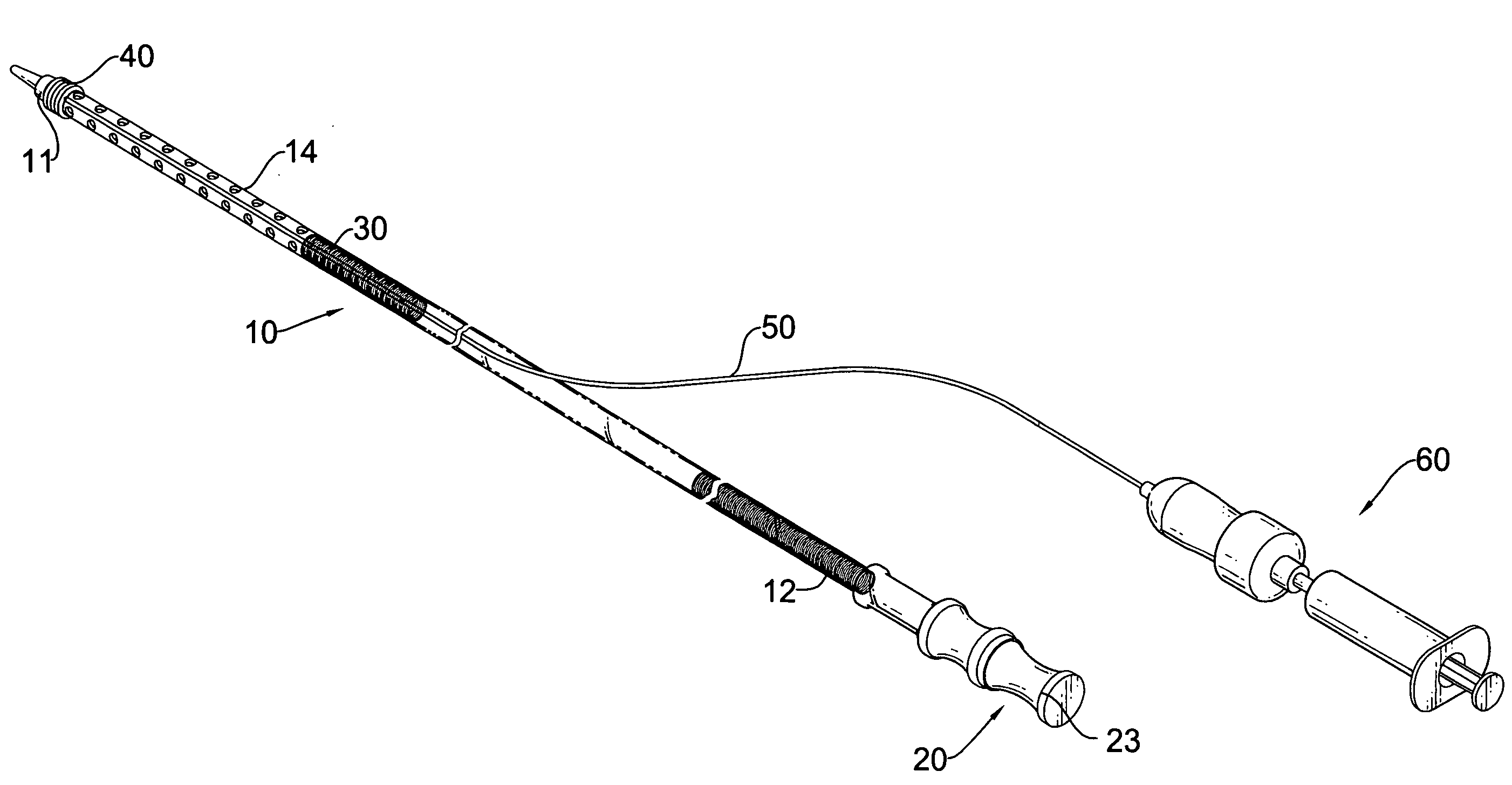
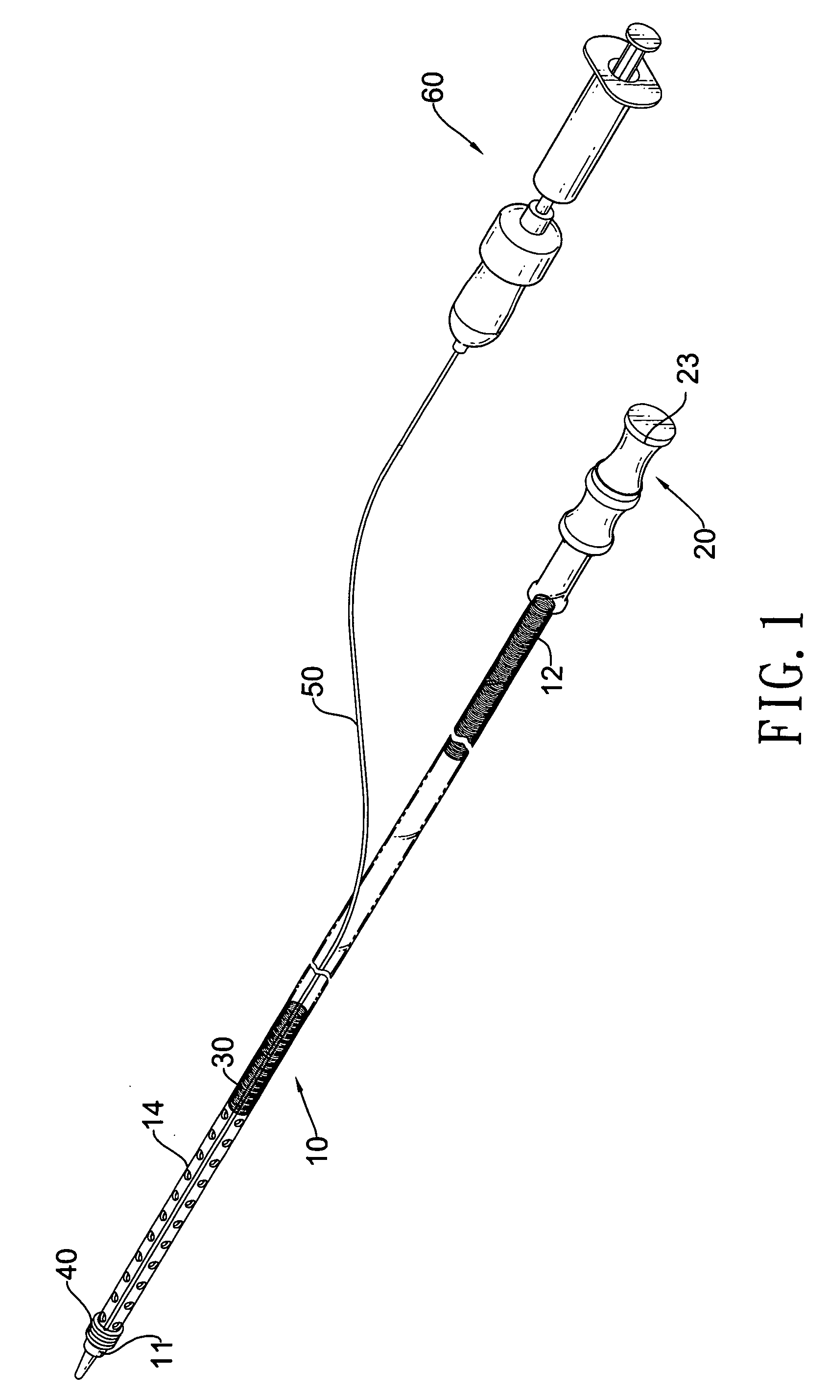
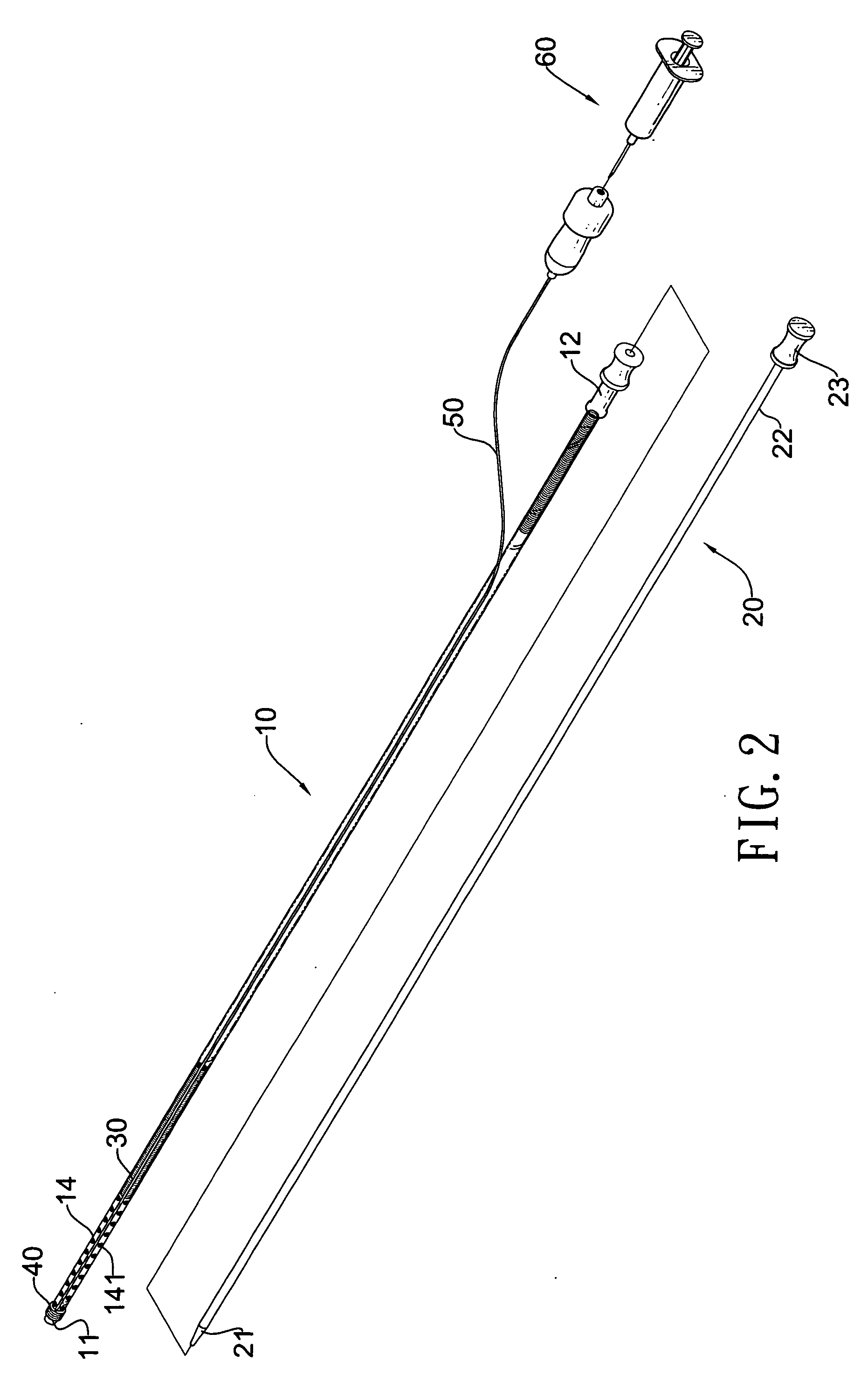
[0024]With reference to FIGS. 1 and 2, a vascular cannula assembly in accordance with the present invention comprises a cannula (10), a tube dilator (20), a supporting helix (30), an inflatable cuff (40), a side tubing (50) and an optional pumping mechanism (60).

[0025]With further reference to FIGS. 3 and 4, the cannula (10) is tubular, has a distal end (11), a proximal end (12), an inner surface (101), an outer surface (102), a valve (13), a drainage segment (14) and an optional tunnel (15). The inner surface (101) defines a passage (103). The passage (103) is formed through the cannula (10) from the distal end (11) to the proximal end (12) and has an opening at the distal end (11) of the cannula (10). The valve (13) may be a resilient membrane having central stellate cleavage, is mounted over and selectively seals the opening at the distal end. The drainage segment (14) is formed adjacent to the distal end (11) of the cannula (10) and has multiple draining apertures (141). The dra...


PUM


Abstract

A vascular cannula assembly has a cannula, a tube dilator, a supporting helix and an inflatable cuff. The cannula has a distal end, a proximal end, a passage and a drainage segment. The drainage segment has multiple draining apertures communicating with the passage. A valve mounted on the distal end of the cannula can prevent air from entering the cannula. The tube dilator is selectively mounted in the passage and has a leading end and a handling end respectively protruding from the distal end and proximal end of the cannula. The supporting helix is mounted in the passage against the cannula. The inflatable cuff is mounted around the cannula between the distal end and the drainage segment. The side tubing is connected to the inflatable cuff. Since the inflatable cuff can be inflated to occlude blood draining from vena cava, use of the vascular cannula assembly can prevent injuries by snaring or looping of vessels during surgical procedures for cardiopulmonary bypass.

Description

BACKGROUND OF THE INVENTION[0001]1. Field of the Invention[0002]The present invention relates to vascular cannula used in draining venous blood during surgical procedures requiring cardiopulmonary bypass.[0003]2. Description of the Prior Arts[0004]The major risk factor for surgical operation lies in massive hemorrhage, especially for cardiac operations. Extracorporeal cardiopulmonary bypass is a major technique utilized to drain adequate volumes of blood from patients during cardiac procedures. In a routine cardiopulmonary bypass, two cannulae are respectively placed into the superior vena cava and the inferior vena cava for collecting venous blood returned to the patient's right atrium. The cannulae are secured with a snare around the vessels and ends of the vessels near the surgical site are further looped or sutured to prevent leakage of blood returned from vena cava or air entering the cannulae. However, looping and snaring of major blood vessels may cause their irreversible inj...

Claims


Application Information

Patent Timeline
IPC IPC(8): A61M39/22A61M25/10A61M1/00A61F2/958
CPCA61M1/3653A61M25/005A61M25/007A61M25/0075A61M1/3659A61M29/00A61M39/22A61M2025/0076A61M2025/0078A61M25/10
Inventor CHEN, WEI-HUI
Owner CHEN WEI HUI
Why Eureka
Try Eureka