Apparatus and method of superconducting magnet cooling

a superconducting magnet and cooling apparatus technology, applied in the direction of superconducting magnets/coils, instruments, sustainable manufacturing/processing, etc., can solve the problems of high cost of superconducting magnets for the provision of helium cryogen, unfavorable use of superconducting magnets, and inability to meet the requirements of superconducting magnets. , to achieve the effect of reducing the amount of cryogen needed, simplifying the design of super

Inactive Publication Date: 2010-09-30
GENERAL ELECTRIC CO
View PDF6 Cites 10 Cited by
  • Summary
  • Abstract
  • Description
  • Claims
  • Application Information

AI Technical Summary

Benefits of technology

The present invention provides a way to make sure that magnetic devices made with high-temperature materials are always cooled properly without requiring too much expensive liquid nitrogen. This makes them easier to use and assemble, which can save money and simplify their operation.

Problems solved by technology

This patent discusses how much it costs to operate and make superconducting magnets due to the high price of helium, which they require. There are technical needs to reduce these expenses by finding ways to lower production and maintenance costs while still achieving effective results with the magnets.

Method used


Image

  • Apparatus and method of superconducting magnet cooling
  • Apparatus and method of superconducting magnet cooling
  • Apparatus and method of superconducting magnet cooling

Examples


Embodiment Construction

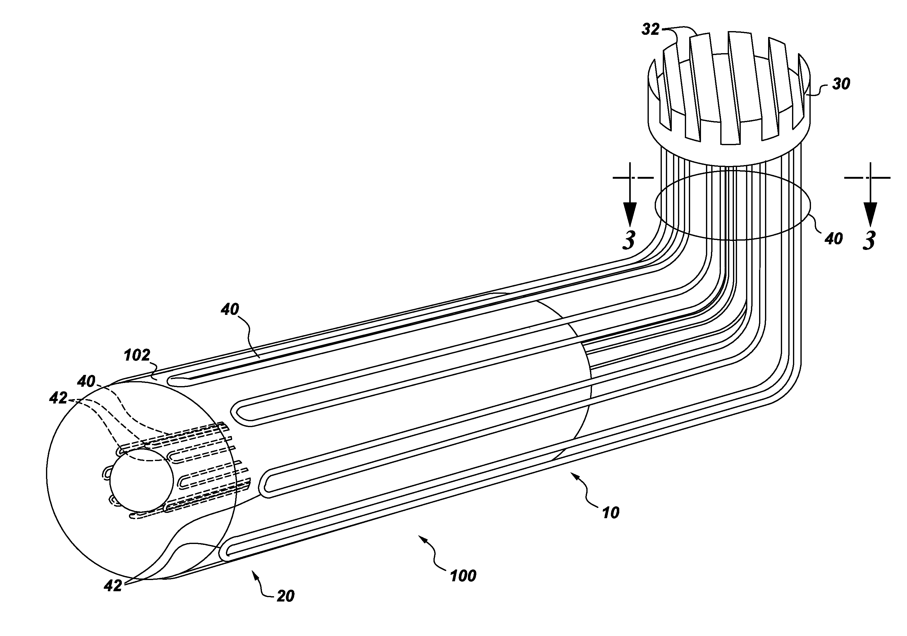
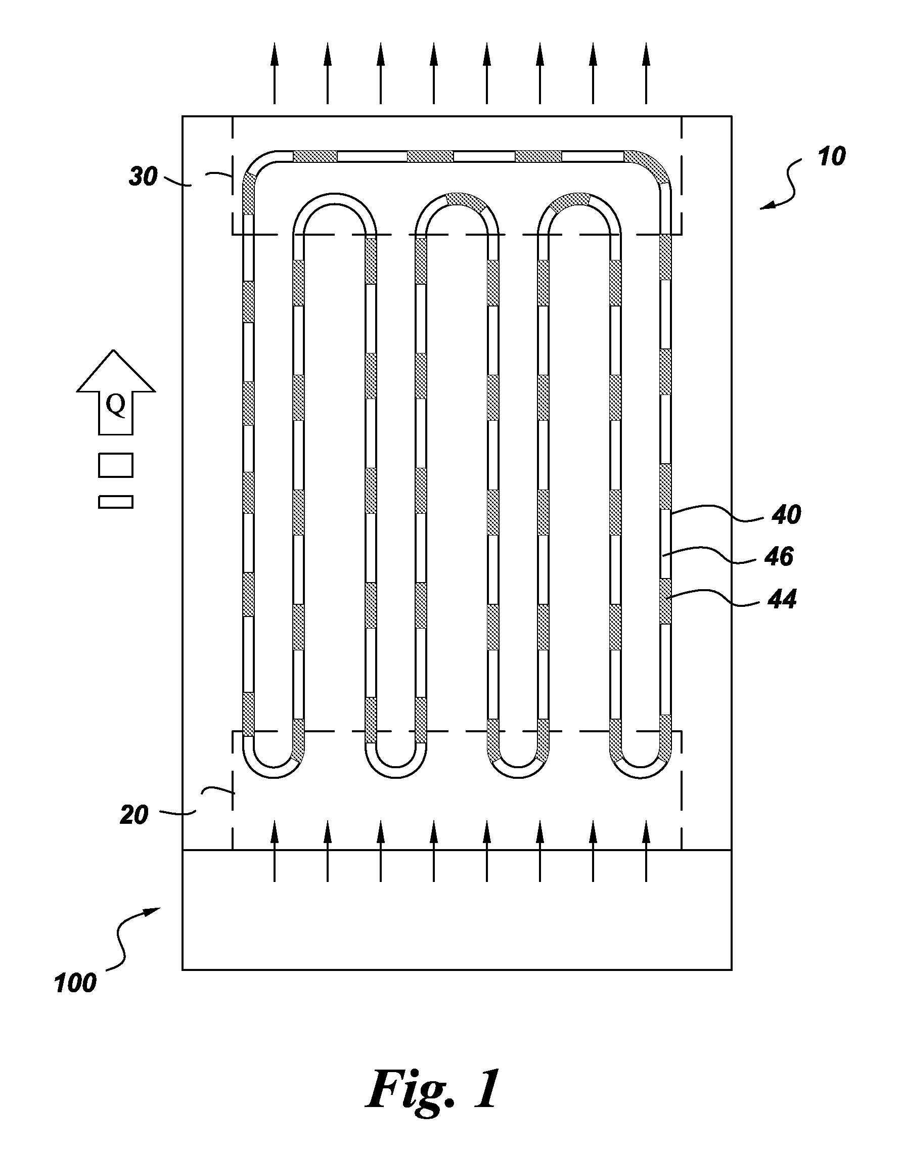
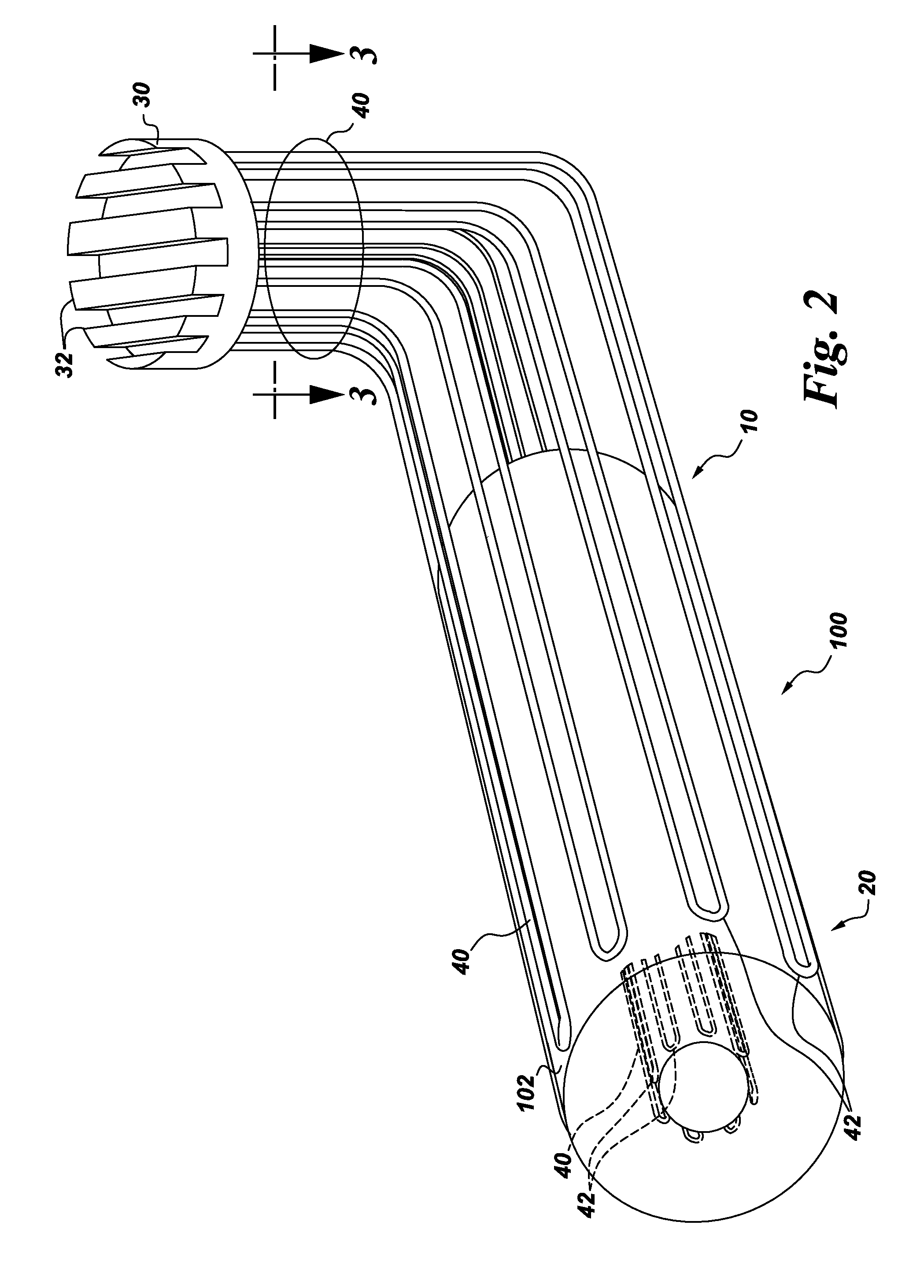
[0017]Aspects of the present invention have been shown to offer advantages over previous methodologies of cooling superconducting magnets. The apparatus and method require no mechanical moving parts (e.g., no pumps, no external pressure fed supply system, no refrigeration “coldbox” for cryogen supply, no helium can-fed flow, etc.) in cooling a superconducting magnet. The cooling method is orientation-independent, which aids in the design and ultimate physical volume and footprint of the superconducting magnet assembly. Design integration of tubing into the existing superconducting magnet geometry is simplified. Further, any hot spots that may arise can immediately be cured by the pulsating slug flow provided by the pulsating heat pipe employed in aspects of the present invention. The design offers other advantages in that it does not require costly helium bath cooling, nor is any cryogen lost during a quench. The proposed capillary tubing can withstand high pressures of several 100 ...


PUM


Abstract

A superconducting magnet assembly and method of cooling a superconducting magnet assembly includes thermally connecting a pulsating heat pipe to the superconducting magnet assembly and adding a liquid cryogen to the pulsating heat pipe. The superconducting magnet assembly also includes a coil former, at least one superconducting solenoid magnet comprising at least one superconducting winding wrapped about the coil former and configured to generate a magnetic field, and at least one pulsating heat pipe thermally connected to the at least one superconducting solenoid magnet. The present invention has been described in terms of specific embodiment(s), and it is recognized that equivalents, alternatives, and modifications, aside from those expressly stated, are possible and within the scope of the appending claims.

Description


Claims


Application Information

Patent Timeline
Owner GENERAL ELECTRIC CO
Why Eureka
Try Eureka