Partition member for cooling passage of internal combustion engine, cooling structure of internal combustion engine, and method for forming the cooling structure

a technology of internal combustion engine and cooling structure, which is applied in the direction of machines/engines, mechanical devices, cylinders, etc., can solve the problems of difficult to accurately arrange the partition member at a desired position in the passage, the edge of the partition member may not be held in tight contact with the inner surface of the passage, and the above-described passage is defined with limited dimension accuracy

Inactive Publication Date: 2010-09-30
TOYOTA JIDOSHA KK +2
View PDF6 Cites 46 Cited by
  • Summary
  • Abstract
  • Description
  • Claims
  • Application Information

AI Technical Summary

Benefits of technology

[0005]Accordingly, it is an objective of the present invention to accurately arrange a partition member, which partitions a groove-like cooling passage in the axial directio

Problems solved by technology

Further, the above-described passage is defined with limited dimension accuracy.
Thus, if the partition member must be fitted independently in the passage of the cylinder block, which is formed through casting, it is extremely difficult to arrange the partition member accurately at a desired position in the passage.
However, e

Method used


Image

  • Partition member for cooling passage of internal combustion engine, cooling structure of internal combustion engine, and method for forming the cooling structure
  • Partition member for cooling passage of internal combustion engine, cooling structure of internal combustion engine, and method for forming the cooling structure
  • Partition member for cooling passage of internal combustion engine, cooling structure of internal combustion engine, and method for forming the cooling structure

Examples


first embodiment

[0045]the present invention will now be described with reference to FIGS. 1A to 6.

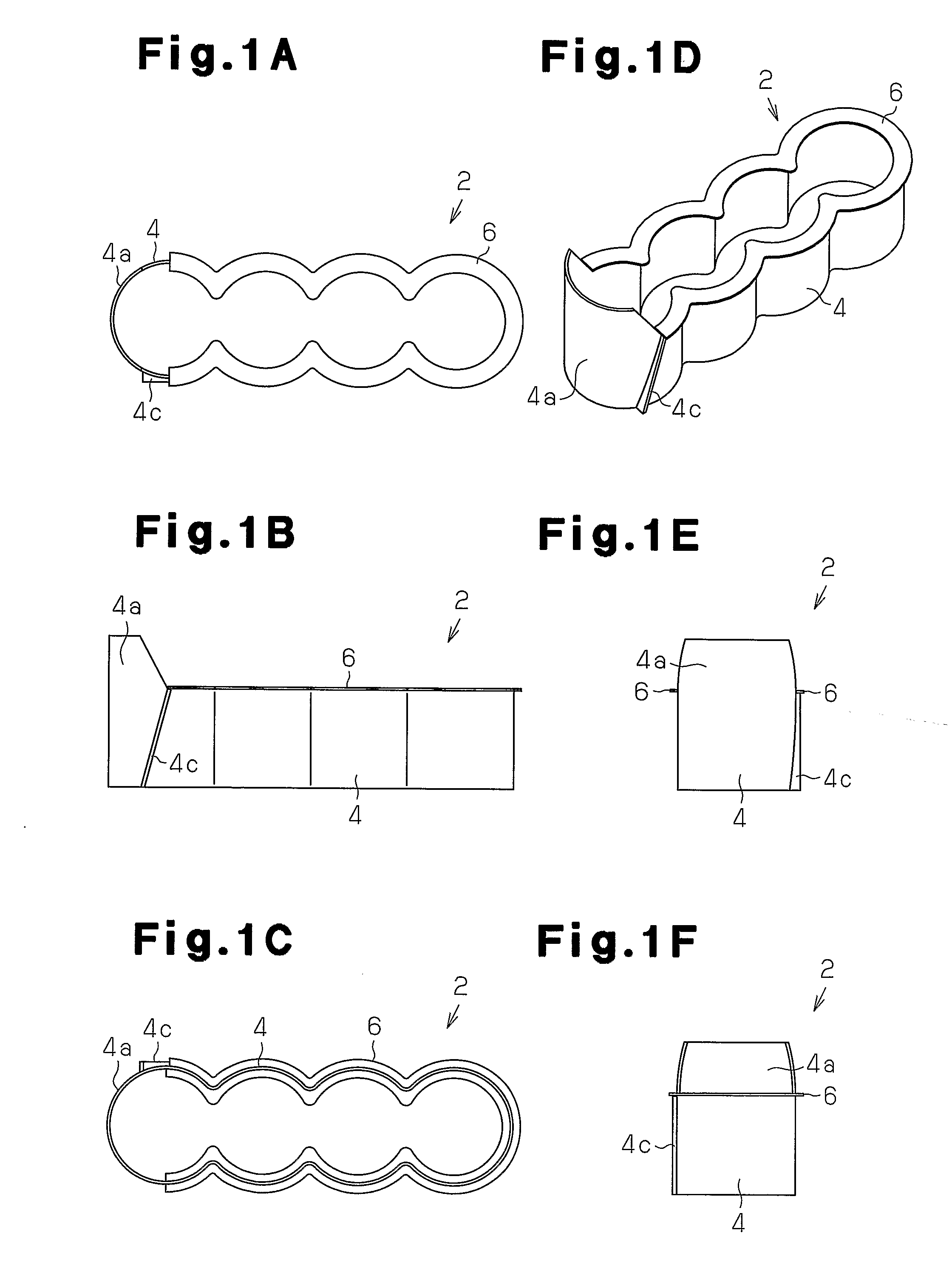
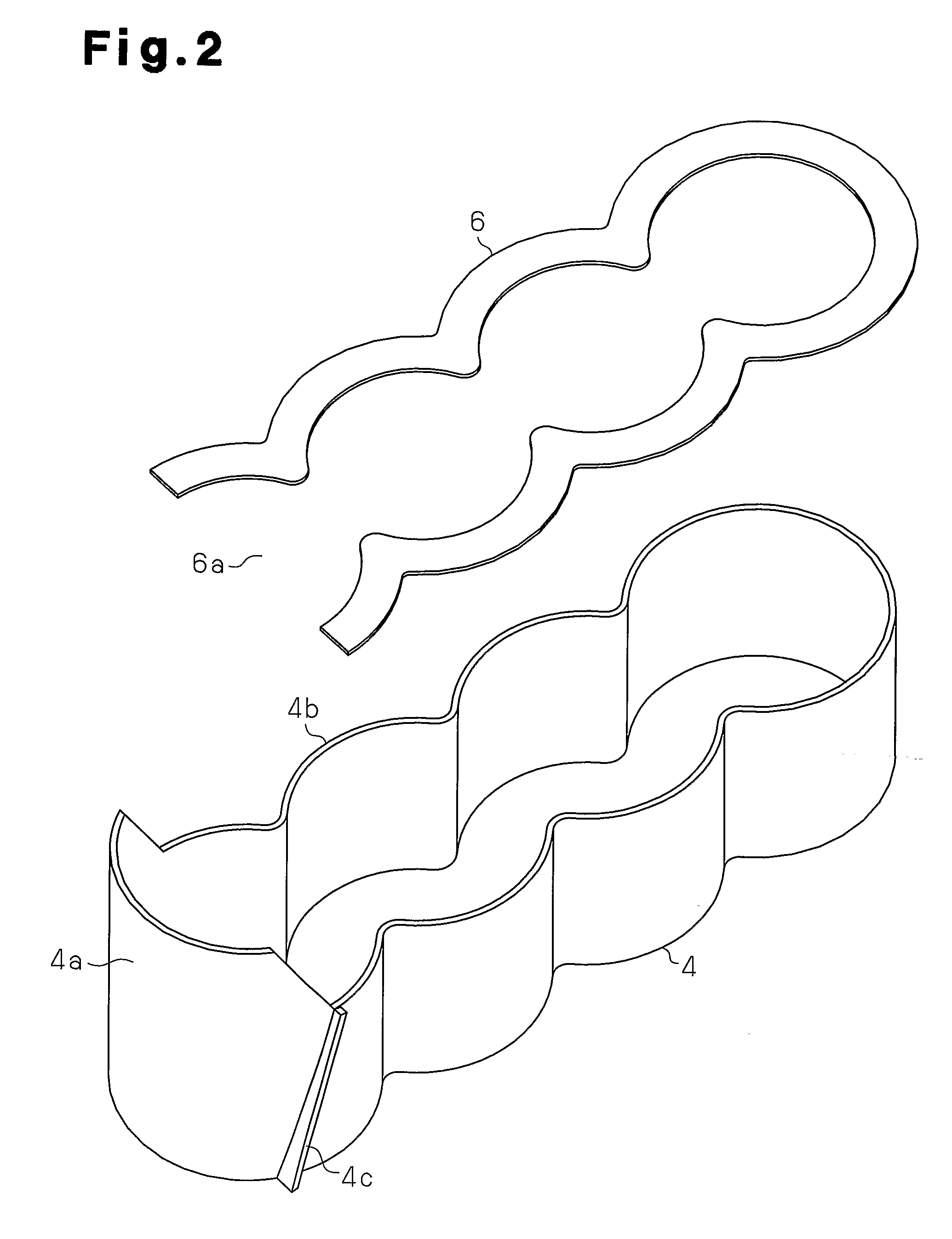
[0046]FIGS. 1A to 2 illustrate the structure of a partition member 2 according to the present invention;

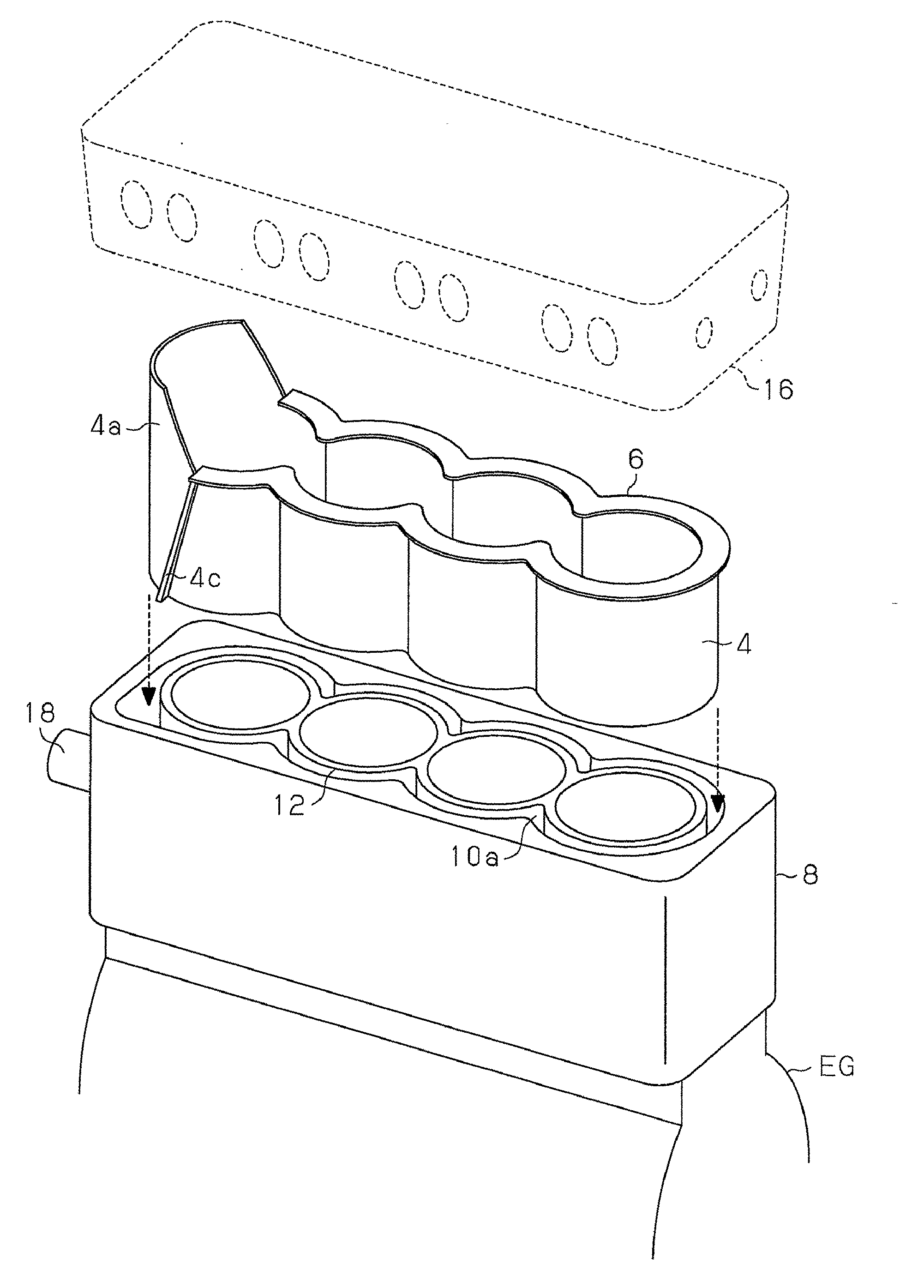
[0047]The partition member 2 includes a spacer 4 and a passage separating member 6. As shown in FIG. 3, which shows the assembly of the partition member 2 in a water jacket 10, the spacer 4 is shaped to be arranged in the water jacket (a groove-like cooling passage in which cooling heat medium flows) 10, which is defined in an open-deck type cylinder block of an engine EG. In other words, the spacer 4 is shaped as a plate the thickness of which is smaller than the width of the water jacket 10. The spacer 4 has a shape resembling connected cylinders that are provided by the number equal to the number of the cylinders (in this embodiment, four cylinders, which are first, second, third, and fourth cylinders). The engine EG is mounted in a vehicle. The width of the water jacket 10 is defined as the dista...

second embodiment

[0065]The second embodiment has the following advantage.

[0066](1) In addition to the advantages of the first embodiment, the flow direction of the coolant is adjusted in such a manner that the coolant from the inlet line 118 flows in one direction (in the counterclockwise direction as viewed from above) through adjustment of the height of the rib 104d provided on the guide wall 104a, as has been described. Further, the ribs 104e, 104f adjust the ratio of the flow rate between the upper portion and the lower portion in the water jacket 110. Thus, without a separate mechanism that adjusts the ratio of the coolant flow rate between the upper and lower portions or the flow direction of the coolant, the partition member 102 adjusts the flow rate and the flow direction of the coolant in such a manner that the difference in the temperature in the axial direction of each cylinder bore decreases.

[0067]A partition member 202 according to a third embodiment of the present invention is shown in...

third embodiment

[0069]The third embodiment has the following advantages.

[0070](1) In addition to the advantages of the first embodiment, the rib 204d formed on the guide wall 204a adjusts the flow direction of the coolant that has been sent from the cooling heat medium inlet line in one direction (in a counterclockwise direction as viewed from above), like the second embodiment.

[0071]Also, since the guide slopes 206a, 206b are formed in the separating member 206, the spacer 204, which exhibits high rigidity, has less projecting portions. It is thus easy to insert the partition member 202 into the water jacket 210.

[0072]The slopes 206a, 206b are provided at the opposite sides, or the inner and outer circumferential surfaces, of the guide wall 204a. This makes it easy to guide the coolant to an upper passage, which is located above the separating member 206. Further, the slopes 206a, 206b are formed of the rubber-like elastic material and an edge of the slope 206a and an edge of the slope 206b are he...


PUM

PropertyMeasurementUnit
Flow rateaaaaaaaaaa
Depthaaaaaaaaaa
Heightaaaaaaaaaa

Abstract

The position of a passage separating member in the axial direction of the cylinder bores is determined by causing a spacer to contact a bottom surface of a water jacket. When the separating member is inserted in the water jacket, the width of the separating member is reduced due to elastic deformation, so that the separating member can be arranged in the water jacket. After being arranged, the separating member tightly contacts the inner surface of the water jacket due to elastic restoration force. The tight contact prevents the separating member from moving upward in the water jacket. As a result, coolant is prevented from moving between the upper portion and the lower portion with respect to the separating member. The advantages of separate cooling of the coolant in the upper and lower portions with respect to the separating member are obtained. This reliably reduces the temperature difference along the axial direction of the cylinder bore forming body.

Description

TECHNICAL FIELD[0001]The present invention relates to a partition member for a cooling passage of an internal combustion engine, a cooling structure of an internal combustion engine, and a method for forming a cooling structure of an internal combustion engine, and, more particularly, to a partition member that divides a groove-like cooling passage defined in a cylinder block of an internal combustion engine into a plurality of passages, a cooling structure employing such partition member, and a method for forming such cooling structure.BACKGROUND ART[0002]A typical cylinder block of an engine has a groove-like cooling passage in which cooling heat medium (coolant) flows. For example, n Japanese Laid-Open Patent Publication No. 2000-345838, discloses a cooling structure in which a cooling passage is divided into a plurality of passages in the direction defined by the depth of the passage. This reduces difference in the temperature in the axial direction of each cylinder bore. Specif...

Claims


Application Information

Patent Timeline
IPC IPC(8): F02F1/14B21K3/00
CPCF01P3/02F02F1/108Y10T29/49231F02F2001/104F02F1/14F02F1/10
Inventor SHIKIDA, TAKASUKEHANAI, SHUICHIHATANO, MAKOTOOKAZAKI, NOBUMITSU
Owner TOYOTA JIDOSHA KK
Why Eureka
Try Eureka