Resistively welded part for an appliance including a surface cleaning apparatus

Active Publication Date: 2010-09-30
OMACHRON INTPROP
View PDF16 Cites 77 Cited by
  • Summary
  • Abstract
  • Description
  • Claims
  • Application Information

AI Technical Summary

Benefits of technology

[0036]A further advantage of the process is that parts that have a complicated geometry may be easily welded witho

Problems solved by technology

If the fluid flow path is under pressure, a fluid such as water is being pumped through a carpet extractor, then this may cause the part to leak.
If the fluid flow path is under vacuum, e.g., air is being drawn through an air flow path of a vacuum c

Method used


Image

  • Resistively welded part for an appliance including a surface cleaning apparatus
  • Resistively welded part for an appliance including a surface cleaning apparatus
  • Resistively welded part for an appliance including a surface cleaning apparatus

Examples


Embodiment Construction

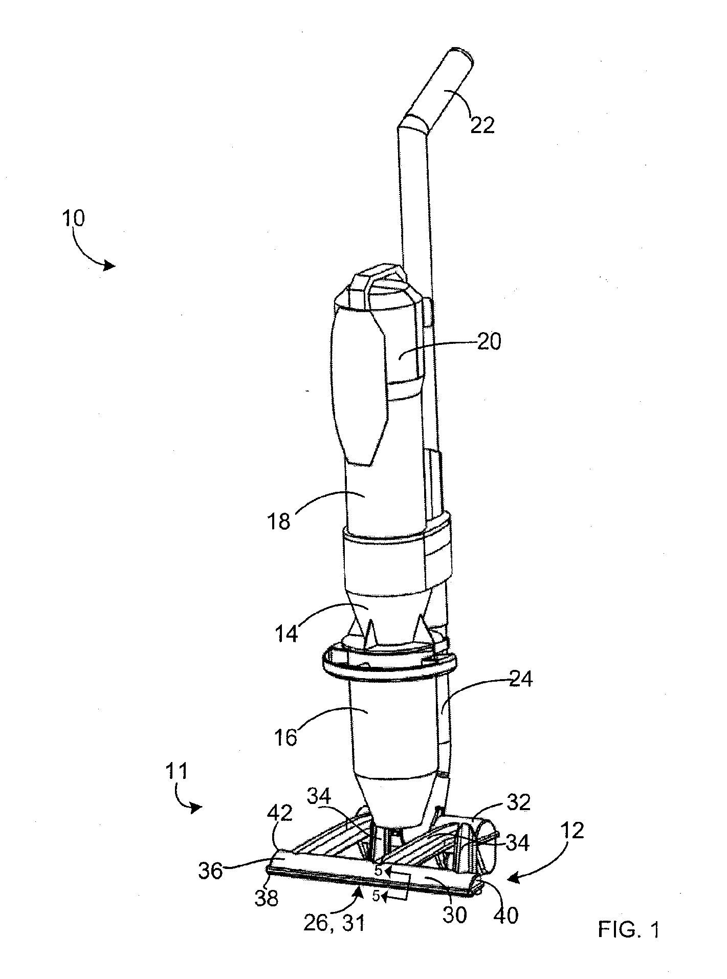
[0047]Referring to FIG. 1, an exemplary surface cleaning apparatus 10 comprising a part according to the present invention is shown. In the embodiment shown, surface cleaning apparatus 10 is an upright vacuum cleaner having an upright section that comprises a surface cleaning head 12, a cyclone 14, a dirt bin 16, a filter housing 18, a motor housed in a motor housing 20. The upright is mounted to a backbone 24, which includes an up flow conduit extending to cyclone 14, and which includes a handle 22. The surface cleaning head 12 comprises a dirty fluid inlet 26, through which air enters surface cleaning apparatus 10. From the surface cleaning head 12, the dirty air enters the up flow conduit of backbone 24, and is directed upwards towards cyclone 14. In cyclone 14, larger dirt particles are separated from the air, and are deposited into dirt bin 16. The air exits the cyclone 14, and passes through optional filter housing 18, where smaller dirt particles are removed from the air. The...


PUM

PropertyMeasurementUnit
Lengthaaaaaaaaaa
Perimeteraaaaaaaaaa
Currentaaaaaaaaaa

Abstract

A part for an appliance, such as a surface cleaning apparatus, a method of making the part, and a method of disassembling the part are disclosed. The part comprises at least first and second plastic members resistively welded together. In some embodiments, the plastic members define a fluid flow cavity, such as a portion of the air flow path through the surface cleaning apparatus.

Description

FIELD OF THE INVENTION[0001]The invention relates to an appliance such as a surface cleaning apparatus, a power tool, a garden tool and a kitchen appliance. In one particular aspect, the invention relates to a part having resistively welded members.BACKGROUND OF THE INVENTION[0002]Surface cleaning apparatuses, such as vacuum cleaners, typically comprise a dirty fluid inlet, a clean fluid outlet, and a fluid flow path extending therebetween. A cleaning element is positioned in the fluid flow path for removing dirt from the fluid. Known cleaning elements include cyclonic cleaning elements, and filter members such as filters and bags. A motor is typically provided in the fluid flow path for drawing fluid in through the dirty fluid inlet, and out through the clean fluid outlet.[0003]The fluid flow path and housings of known vacuum cleaners may consist of numerous parts, at least some of which are typically fabricated by molding two or more mating plastic members and subsequently securin...

Claims


Application Information

Patent Timeline
IPC IPC(8): B32B3/02B32B37/06
CPCA47L5/24A47L9/122A47L9/1666A47L9/20A47L7/0028A47L7/0038Y10T428/17A47L9/1658A47L9/165A47L9/1608Y10T156/1158Y10T428/24488Y10T428/19A47L9/1683B29C65/342B29C65/3432B29C66/54B29L2031/7406B29C66/73921B29C66/1312B29C66/12441B29C66/1122B29C66/949B29C66/71B29L2031/3481B29L2031/749B29C65/3476B29C66/244B29K2069/00B29K2023/06B29K2023/12B29K2055/02A47L9/1625
Inventor CONRAD, WAYNE ERNEST
Owner OMACHRON INTPROP
Why Eureka
Try Eureka