Gas flow path structure and substrate processing apparatus

a technology of gas flow path and substrate, which is applied in the direction of electrical apparatus, electric discharge tubes, basic electric elements, etc., can solve the problems of low flexibility, low reliability, and low flexibility so as to improve the reliability of gas flow path structure and minimize particle generation

Active Publication Date: 2010-09-30
TOKYO ELECTRON LTD
View PDF7 Cites 387 Cited by
  • Summary
  • Abstract
  • Description
  • Claims
  • Application Information

AI Technical Summary

Benefits of technology

[0016]In view of the foregoing, the present disclosure provides a gas flow path structure capable of supplying a gas to a movable electrode with a high reliability without raising a layout problem in securing an installation space; and also provides a substrate processing apparatus using the gas flow path structure.
[0019]In the gas flow path structure, a guide member, which suppresses bending of the first displacement-absorbing pressure partition wall in a direction perpendicular to a lengthwise direction thereof, is installed so as to face an outer peripheral portion of the first displacement-absorbing pressure partition wall.
[0023]The above-mentioned gas flow path structure and the above-mentioned substrate processing apparatus include: the supporting member configured to support either one of the mounting electrode and the facing electrode while allowing the one electrode to be movable with respect to the other; the first displacement-absorbing pressure partition wall having a ring shape and installed at the outer peripheral portion of the supporting member so as to be concentric with the supporting member, the first partition wall serving to absorb the displacement (moving distance) of the one electrode with respect to the wall surface of the processing chamber at the penetration portion where the supporting member penetrates the wall surface and serving to seal the inside of the processing chamber against the ambient atmosphere around the supporting member; and the second displacement-absorbing pressure partition wall having a ring shape and installed at the outer peripheral portion of the first displacement-absorbing pressure partition wall so as to be concentric with the first displacement-absorbing pressure partition wall. Further, the first ring-shaped gas flow path is formed by the first displacement-absorbing pressure partition wall and the second displacement-absorbing pressure partition wall. Thus, the gas flow path absorbing the displacement according to the movement of the electrode may be provided within the processing chamber. With this configuration, no layout problem may be caused in securing the installation space for the gas flow path structure. Furthermore, the gas can be supplied stably by absorbing the displacement (moving distance) of the movable electrode effectively, and reliability of the gas flow path structure can be improved.
[0025]In the gas flow path structure, the guide member, which suppresses bending of the first displacement-absorbing pressure partition wall in the direction perpendicular to the lengthwise direction thereof, is installed so as to face the outer peripheral portion of the first displacement-absorbing pressure partition wall. Therefore, buckling (deformation) of the first partition wall that is exposed to an inside atmosphere and an outside vacuum can be suppressed.
[0027]In the gas flow path structure, the displacement-absorbing pressure partition walls are bellows. Therefore, since the gas can be supplied successfully by absorbing the displacement of the movable electrode according to its movement, the reliability of the gas flow path structure can be improved, and particle generation can be minimized.

Problems solved by technology

As shown in FIG. 5, however, since a flexible tube 108 includes a thin metal pipe 109 on which a plurality of waves is formed; and a metal mesh blade 110 enclosing the metal pipe 109, it has a relatively high stiffness against bending and thus is lack of flexibility.
Thus, when such a flexible tube is employed together with a movable component having a long displacement (moving distance), it may be broken in an early stage.
That is, the flexible tube is not designed to be repetitively bent, and it has a finite lifetime due to an irregular breakdown.
Accordingly, the flexible tube needs to be replaced in a cycle of about one year, thus raising a safety issue related to the lifetime.
Further, an integrally formed bellows not designed to be bent repetitively raises the same problem as that of the flexible tube.
Thus, it is difficult to use such a bellows as the gas feed pipe for supplying the processing gas into the shower head 103 which frequently moves up and down.
Since, however, the rotary joint has a physical sliding part, it may be difficult to avoid particle generation.
Thus, its application to the substrate processing apparatus in which the particle generation largely affects a quality of a final product is deemed to be unpractical.
Accordingly, it is difficult to secure the installation space on a top surface of an upper unit of the substrate processing apparatus including many components.
Thus, there arises a layout problem.

Method used


Image

  • Gas flow path structure and substrate processing apparatus
  • Gas flow path structure and substrate processing apparatus
  • Gas flow path structure and substrate processing apparatus

Examples


Embodiment Construction

[0034]Hereinafter, embodiments of the present disclosure will be described with reference to the accompanying drawings.

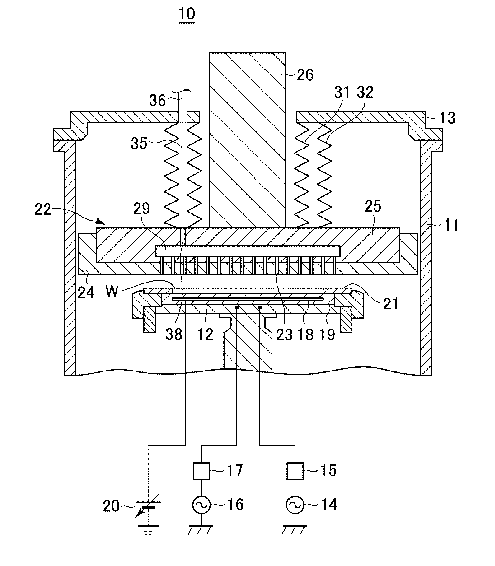
[0035]FIG. 1 is a cross sectional view schematically illustrating a configuration of a substrate processing apparatus having a gas flow path structure in accordance with an embodiment of the present disclosure. The substrate processing apparatus is configured to form so as to perform dry etching process on a wafer.

[0036]In FIG. 1, a substrate processing apparatus 10 includes a cylindrical chamber (processing chamber) 11 that accommodates a wafer W having a diameter of, e.g., about 300 mm. Installed in a lower part of the chamber 11 is a circular plate-shaped susceptor (mounting electrode) 12 configured to mount thereon the wafer W for a semiconductor device. An upper part of the chamber 11 is covered by an openable / closable cover 13 having a circular plate shape.

[0037]The inside of the chamber 11 is depressurized by a TMP (Turbo Molecular Pump), a DP (Dry Pump) (bot...


PUM

PropertyMeasurementUnit
frequencyaaaaaaaaaa
frequencyaaaaaaaaaa
moving distanceaaaaaaaaaa

Abstract

A substrate processing apparatus includes: a depressurizable processing chamber 11; a shaft 26 supporting a facing electrode 24 provided within the processing chamber 11 while allowing the facing electrode 24 to be movable with respect to a mounting electrode 12; a first ring-shaped bellows 31 concentrically installed at an outer peripheral portion of the shaft 26; and a second bellows 32 concentrically installed at an outer peripheral portion of the first bellows 31. The first bellows 31 absorbs a displacement of the facing electrode 24 with respect to a wall surface 13 at a penetration portion where the shaft 26 penetrates the wall surface 13 of the processing chamber 11, and seals the inside of the processing chamber 11 against the ambient atmosphere around the shaft 26. A ring-shaped gas flow path 35 is formed by the first bellows 31 and the second bellows 32.

Description

CROSS-REFERENCE TO RELATED APPLICATION[0001]This application claims the benefit of Japanese Patent Application No. 2009-086036 filed on Mar. 31, 2009, and U.S. Provisional Application Ser. No. 61 / 242,609 filed on Sep. 15, 2009, the entire disclosures of which are incorporated herein by reference.FIELD OF THE INVENTION[0002]The present disclosure relates to a gas flow path structure and a substrate processing apparatus. More particularly, the present disclosure relates to a gas flow path structure used in a substrate processing apparatus having a movable electrode, and to a substrate processing apparatus including the gas flow path structure.BACKGROUND OF THE INVENTION[0003]A substrate processing apparatus, which performs a plasma process on a semiconductor wafer (hereinafter, simply referred to as a “wafer”) serving as a substrate, includes a chamber (processing chamber) that accommodates a wafer therein and can be depressurized; a susceptor (mounting table) installed at a lower par...

Claims


Application Information

Patent Timeline
Patent Type & Authority Applications(United States)
IPC IPC(8): H01L21/465
CPCH01J37/32568
Inventor HAYASHI, DAISUKE
Owner TOKYO ELECTRON LTD
Why Eureka
Try Eureka