Oblique blended wing body aircraft

a blended, aircraft technology, applied in the field of flying objects, can solve the problems of difficult integration of the engine into the wing, large surface area, and high friction drag of the skin, and achieve the effect of low compressibility drag and low wetted area

Active Publication Date: 2010-09-30
ADVANCED PROD DEV
View PDF24 Cites 31 Cited by
  • Summary
  • Abstract
  • Description
  • Claims
  • Application Information

AI Technical Summary

Benefits of technology

[0009]The present invention combines the benefits of a Blended Wing Body aircraft and an all flying Oblique Wing Aircraft. The invention combines the low w...

Problems solved by technology

The small chord length and limited thickness of the wing made integrating the engine into the wing more difficult and in order to have an aircraft with a thick enough wing that passengers could stand up in a cabin the aircraft had to be very large carrying approximately six hundred passengers.
From this we can determine that this aircraft has a large amount of surface area to internal volume ratio and as such will have a lot of skin friction drag in both high and low speed configurations.
Also because the circle is small and there is a finite limit to the thickness to chord length of the airfoil used on this flying wing, we know the thickness of the vehicle will not be v...

Method used


Image

  • Oblique blended wing body aircraft
  • Oblique blended wing body aircraft
  • Oblique blended wing body aircraft

Examples


Embodiment Construction

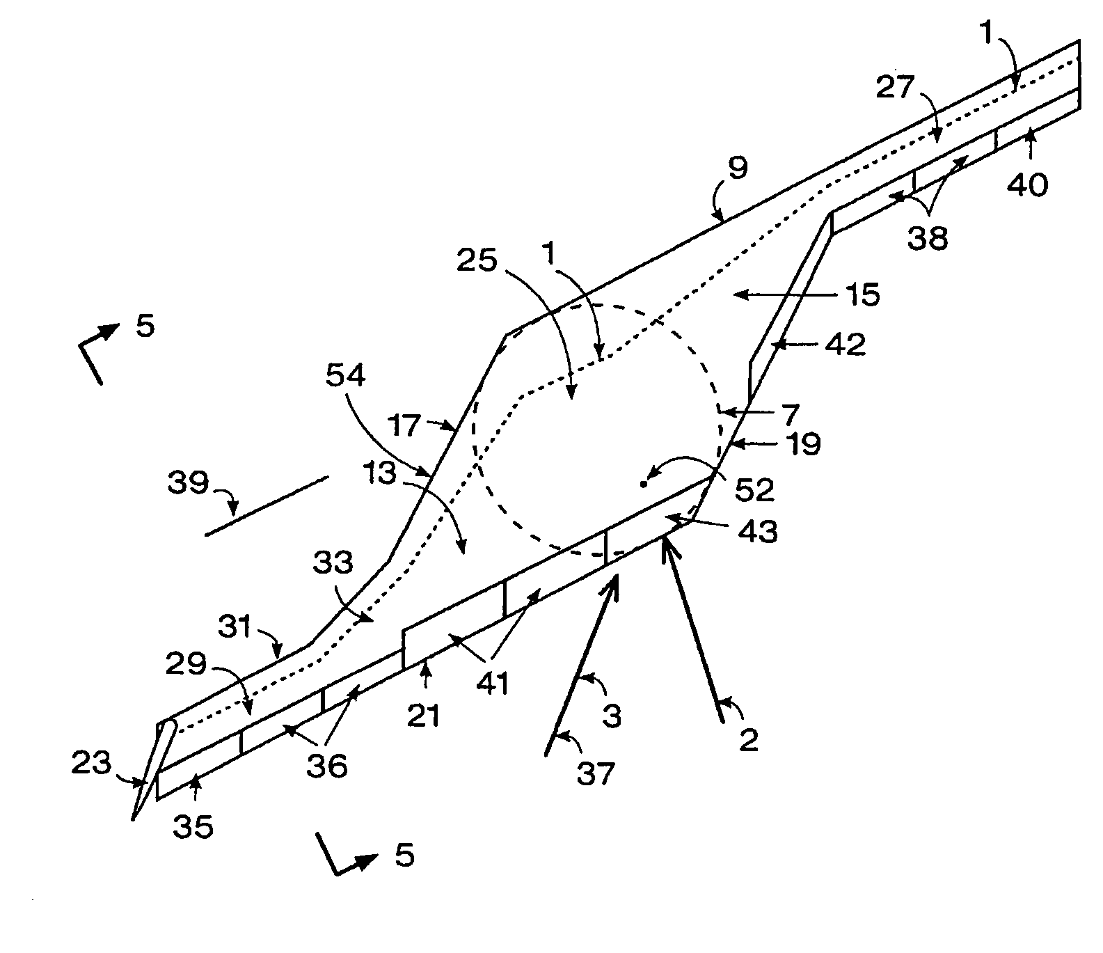
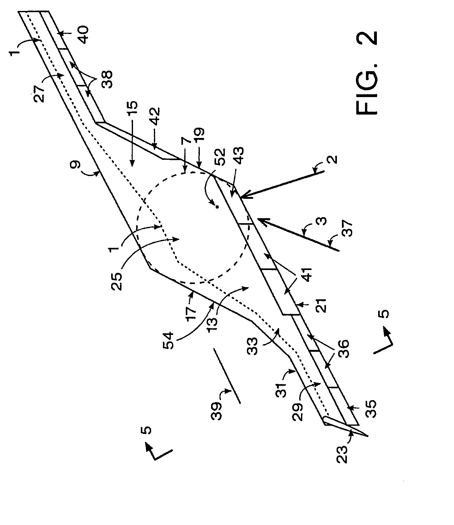
[0015]Referring to FIG. 2, a center airfoil section, called herein the “center body”25, is designed by starting off with a circle 7 as shown in dashed lines at the center of the aircraft planform. Tapering transition areas 15 and 13 are added on either side of the circle to form left and right sides of the center body 25 and a forward swept wing 27 and an aft swept wing 29 are then attached to the center body 25 as shown in FIG. 2 plan view. The center body 25 is itself a wing segment with airfoil cross-sections. The forward swept wing 27 preferably has a leading edge 9 that is an extension of the leading edge of the center body's forward swept transition area 15. The aft swept wing 29 has its aerodynamic center behind the pitch axis 39 so it is helpful in stabilizing the vehicle in pitch about the pitch axis 39. The pitch axis 39 for this configuration is defined parallel to the quarter chord of the forward swept wing but passing through the vehicle center of gravity as shown in FI...


PUM


Abstract

An oblique wing aircraft (1) designed for reduced surface area to volume ratio. The aircraft has an oblique wing comprising a forward swept wing segment (27) on one side of the wing and an aft swept wing segment (29) on the opposite side of the wing. A center oblique airfoil section (25) connects the forward and aft swept wing segments. The center oblique airfoil section has a larger chord near its centerline than the chords of either of the forward or aft swept wing segments. The chord of the center oblique airfoil section tapers down more rapidly than the forward or aft wing segments as the center oblique airfoil section extends outboard toward the forward and aft swept wings. The center oblique airfoil section is not shaped solely to function as a circular fairing to fill the gap between an oblique wing and a fuselage at different oblique wing angles, nor is it a second wing in an X wing configuration. Preferably, the aircraft is an all-wing aircraft.

Description

RELATED APPLICATIONS[0001]This application claims priority to U.S. Provisional Patent Application Ser. No. 60 / 935,758, filed Aug. 29, 2007, which is hereby incorporated by reference.TECHNICAL FIELD[0002]The present invention relates to flying objects designed to fly fast enough that compressibility drag becomes significant.BACKGROUND ART[0003]In the past people have proposed blended wing body aircraft like the B-2 bomber and people have also proposed all flying Oblique Wings as shown in FIG. 1 with an elliptical or near elliptical planform.[0004]Blended Wing Body aircraft like the B-2 achieve lower drag than a pure flying wing by minimizing the surface area exposed to the airflow. They do this by having a center body that is as close as practical to circular in planform but usually with a pointed nose on the front to reduce compressibility drag and with wings attached to the sides to increase the wingspan for reduced induced drag which is drag due to creating lift. A wing with a cir...

Claims


Application Information

Patent Timeline
IPC IPC(8): B64C39/10B64C3/00B64C17/10
CPCB64C30/00B64C39/10B64C3/10Y02T50/12B64C2039/105Y02T50/10B64C39/029
Inventor MCDONNELL, WILLIAM R
Owner ADVANCED PROD DEV
Why Eureka
Try Eureka