Gas level display controller, gas level display device, and gas level display control method

Active Publication Date: 2010-09-30
TOYOTA JIDOSHA KK
View PDF2 Cites 26 Cited by
  • Summary
  • Abstract
  • Description
  • Claims
  • Application Information

AI Technical Summary

Benefits of technology

[0018]In general, when the compressed gas remaining in the tank has a relatively large amount and a relatively high pressure level, the measurement of the pressure of the compressed gas in the tank has a relatively high detection accuracy. The relatively high detection accuracy leads to a relatively high calculation accuracy in the calculation of the mass of the compressed gas in the tank. When the compressed gas remaining in the tank decreases to a relatively small amount and has a relatively low pressure level, on the other hand, the measurement of the pressure of the compressed gas in the tank has a relatively low detection accuracy. The relatively low detection accuracy leads to a relatively low calculation accuracy in the calculation of the mass of the compressed gas in the

Problems solved by technology

This may undesirably cause the display of the remaining amount or the level of the compressed gas in the tank to include erroneous display, whi

Method used


Image

  • Gas level display controller, gas level display device, and gas level display control method
  • Gas level display controller, gas level display device, and gas level display control method
  • Gas level display controller, gas level display device, and gas level display control method

Examples


first embodiment

A. First Embodiment

A1. Gas Level Display System

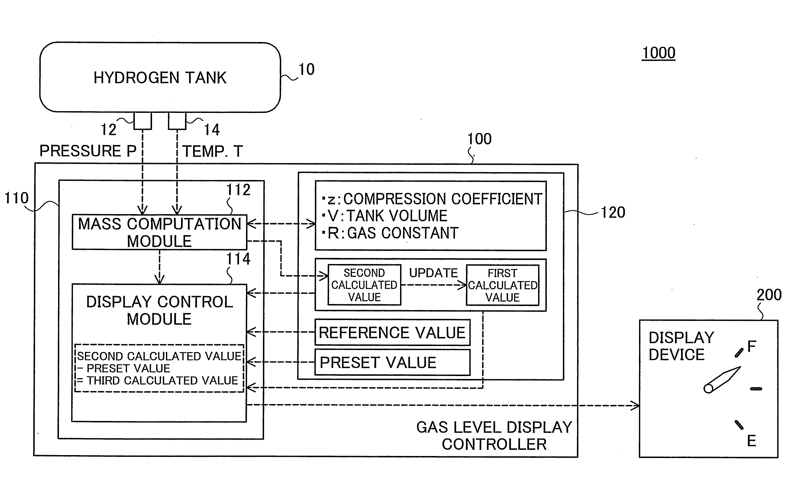
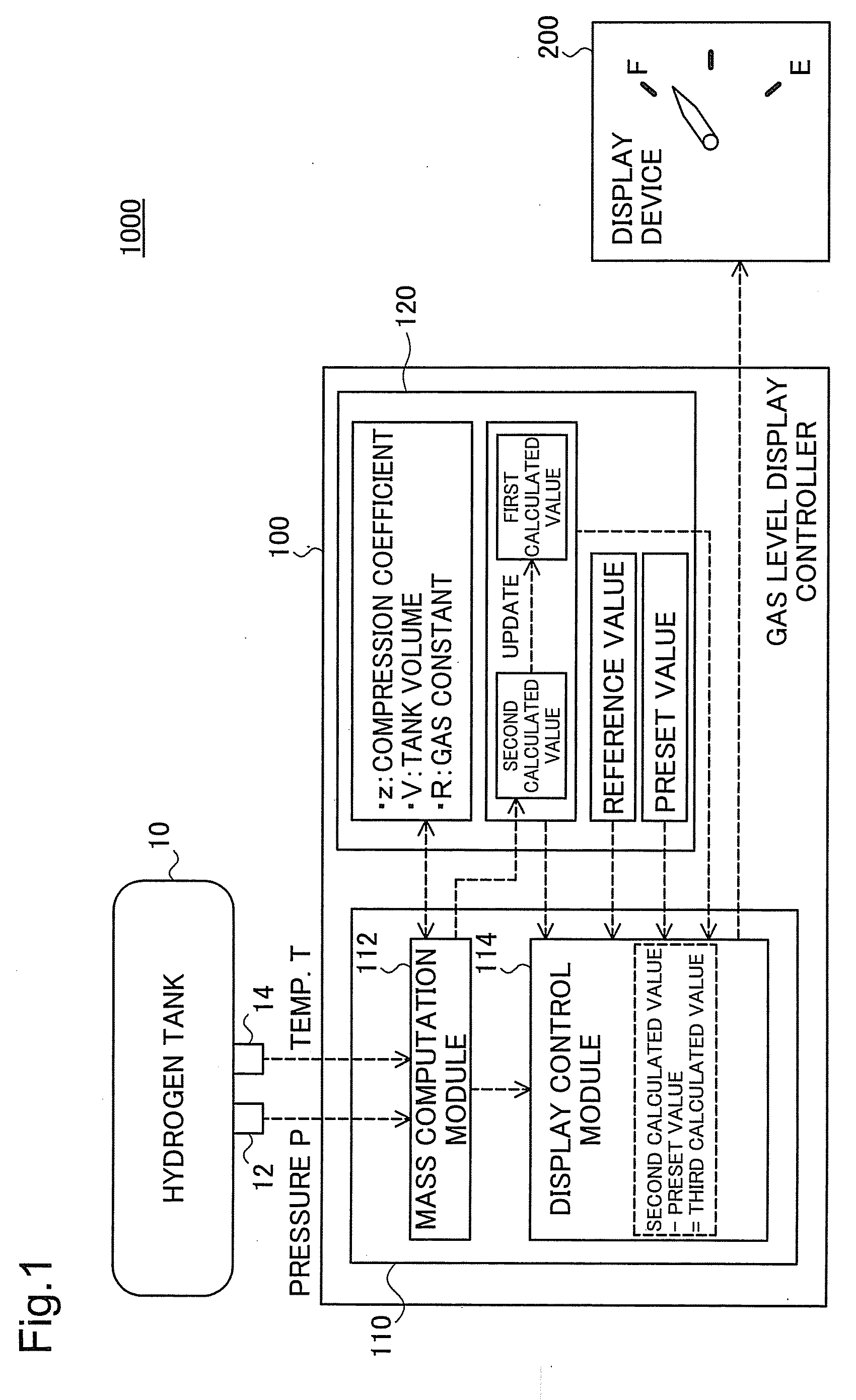
[0030]FIG. 1 is an explanatory view illustrating the schematic configuration of a gas level display system 1000 including a gas level display controller according to one embodiment of the invention. The gas level display system 1000 may be mounted on, for example, an electric vehicle driven with driving power from a motor, which consumes supply of electric power generated in fuel cells through an electrochemical reaction of hydrogen with oxygen.

[0031]As illustrated, the gas level display system 1000 includes a hydrogen tank 10, a gas level display controller 100, and a display device 200.

[0032]The hydrogen tank 10 is equipped with a pressure sensor 12 arranged to measure a pressure P of compressed hydrogen stored in the hydrogen tank 10 and with a temperature sensor 14 arranged to measure a temperature T of the compressed hydrogen stored in the hydrogen tank 10.

[0033]The gas level display controller 100 has a CPU 110 and memories 120. T...

second embodiment

B. Second Embodiment

B1. Gas Level Display System

[0052]A gas level display system 1000 according to a second embodiment of the invention has a similar configuration to that of the gas level display system 1000 of the first embodiment shown in. FIG. 1. In the gas level display system 1000 of the second embodiment, a gas level display control process performed by the CPU 110 of the gas level display controller 100 in the second embodiment is partly different from the gas level display control process performed in the first embodiment. The gas level display control process of the second embodiment is discussed below.

B2. Gas Level Display Control Process

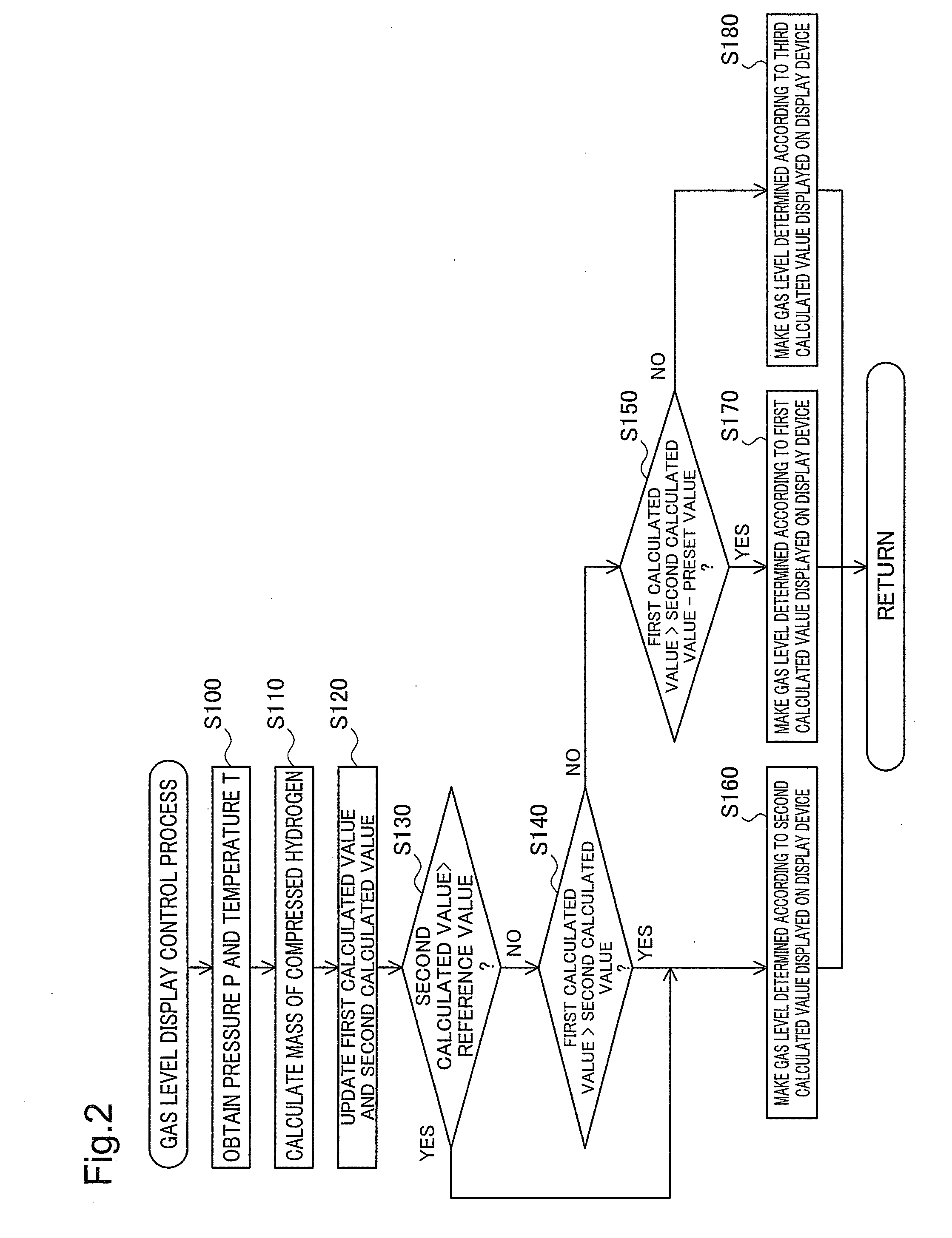
[0053]FIG. 3 is a flowchart showing a flow of the gas level display control process performed in the second embodiment. Like the first embodiment, the CPU 110 repeatedly executes this gas level display control process after activation of the gas level display controller 100.

[0054]As clearly understood from the comparison between the flowc...

modification 1

C1. Modification 1

[0060]Application of the invention to the storage of the compressed hydrogen in the hydrogen tank 10 is described in the above embodiments. The principle of the invention is, however, not restricted to the storage of the compressed hydrogen but is applicable in general to storage of any compressed gas in a gas tank.


PUM


Abstract

A gas level display controller sequentially calculates a mass of a compressed gas stored in a tank and makes a comparison between a first calculated value obtained at a first timing and a second calculated value obtained at a second timing later than the first timing. When the second calculated value is smaller than the first calculated value, the gas level display controller makes the remaining amount of the compressed gas in the tank displayed on a predetermined display device, based on the second calculated value. When the second calculated value is not smaller than the first calculated value, the gas level display controller makes the remaining amount of the compressed gas in the tank displayed on the predetermined display device, based on the first calculated value. This arrangement effectively prevents the display of the remaining amount of the compressed gas in the tank on the display device from including erroneous display, which indicates an increase of the gas level, regardless of no additional supply of the compressed gas into the tank.

Description

TECHNICAL FIELD[0001]The present invention relates to a technique of causing a remaining amount of a compressed gas stored in a tank to be displayed on a predetermined display device.BACKGROUND ART[0002]Various techniques have been proposed to display the remaining amount of a compressed gas stored in a tank (see, for example, JP-A-2005-240854). The prior art technique disclosed in this cited reference JP-A-2005-240854 calculates the mass of a compressed gas fuel (compressed gas) stored in a tank from the pressure and the temperature of the compressed gas fuel and displays the remaining amount of the compressed gas fuel in the tank. Other known relevant techniques include those disclosed in JP-A-2004-63205, JP-A-59-31415, JP-A-2006-112492, and JP-A-2006-242839.[0003]In the prior art technique disclosed in this cited reference JP-A-2005-240854, the outputs of, for example, a pressure sensor, a temperature sensor, and respective electronic components of a gas level display device incl...

Claims


Application Information

Patent Timeline
IPC IPC(8): G08B17/10
CPCF17C13/023G01G17/04F17C2221/012F17C2223/0123F17C2223/035F17C2223/036Y02E60/321F17C2250/0408F17C2250/043F17C2250/0439F17C2250/0495F17C2260/024F17C2250/032Y02E60/32
Inventor KANIE, NAOKI
Owner TOYOTA JIDOSHA KK
Why Eureka
Try Eureka