Method and Apparatus for Thermal Management of a Radio Frequency System

a radio frequency system and thermal management technology, applied in the direction of electrical apparatus casings/cabinets/drawers, instruments, semiconductor/solid-state device details, etc., can solve the problem of reducing the thermal resistance between the heat generating portions of the flip chip circuit and the heat sink, and achieves low noise, large development costs, and effective cooling of a single active panel

Active Publication Date: 2010-09-30
RAYTHEON CO
View PDF82 Cites 44 Cited by
  • Summary
  • Abstract
  • Description
  • Claims
  • Application Information

AI Technical Summary

Benefits of technology

[0023]The thermal management system described herein, on the other hand, reduces the problem of air-cooling phased arrays of various sizes to the problem of air-cooling a single active panel (e.g. a six inch (wide) by ten inch (high) by six inch (deep) unit at X-Band). It has been recognized that by being able to effectively cool a single active panel, it is possible to air-cool an entire active phased array made from a plurality of such active panels. Furthermore, a plurality of like active panels can be assembled to provide a large phased array (e.g. a large AESA) without incurring large development costs (sometimes referred to as non-recurring engineering or NRE costs) associated with analysis and design of a new thermal management system for active phased arrays.
[0024]The modular system described herein also provides performance flexibility. Desirable RF output power, noise figure, etc. of T / R channel electronics can be achieved by utilizing a wide range of surface mounted semiconductor electronics. Since the active components are mounted on an external surface of the active panel, the same panel can be used in a wide range of applications by merely mounting (e.g. as flip-chips) active circuits having different characteristics (e.g. high power or low power circuits) to the active panel. The heat sink, fan and other portions of the thermal management system can be adjusted accordingly (e.g. by selection of different fan sizes, duct sizes, or heat sink materials). The active panel thus provides design flexibility in that it is designed to accept at least the following semiconductor electronics: RF CMOS based upon commercial silicon technology and selected to provide desirable RF characteristics (e.g. lowest output power and highest noise figure); silicon germanium (SiGe) selected to provide desirable RF characteristics (e.g. RF output power levels and noise figures in the X-band frequency range); gallium arsenide (GaAs) selected to provide desirable RF characteristics such as RF output power densities and low noise figure (it should be appreciated that heretofore, AESA's at L-Band and above have been enabled by GaAs technology); as well as emerging technologies such as gallium nitride (GaN) which demonstrates relatively high power, efficiency, and power density (Watts / mm2) characteristics compared with all existing semiconductor technologies.
[0025]The thermal management system described herein efficiently transfers heat (i.e. thermal energy) from an active panel (and in particular from active circuits mounted on the active panel) to a heat sink. By reducing the number of thermal interfaces between the active circuits and the heat sink, the thermal resistance, and therefore temperature rise, from the active circuits to the heat sink is minimized. The fans and ducts are configured to efficiently transfer the dissipated thermal energy away from the heat sink (and thus the active panel) and thus the thermal management system maintains the temperature of an integrated active panel assembly (IAPA) within a desired operating temperature range. Cooling individual portions of an array antenna (e.g. by cooling each of the IAPAs individually) reduces temperature gradients across the array antenna. In a preferred embodiment, the active circuits are mounted on the active panel as flip-chip circuits.
[0026]By using a modular approach to thermal management of an antenna array, a distributed cooling approach is provided. The thermal management system described herein thus provides a technique for distributed air cooling of a large antenna aperture. The thermal management technique is distributed since individual blocks of cooling systems (e.g. a plurality of blocks) are used to cool individual portions of an array antenna such as a panel array antenna. Since cooling blocks are used, the approach can be scaled to large array antennas (i.e. by simply adding more cooling blocks). Furthermore, by cooling individual portions of an array antenna (e.g. by cooling each of the active panels individually) temperature gradients across the array antenna are reduced. Thus, in this manner a distributed (vs. centralized) air cooled AESA can be provided.

Problems solved by technology

Coupling a heat sink directly to the flip chip mounted circuits disposed on the surface of the active panel (PWB) reduces the number of interfaces between the heat sink and the flip chip circuits and thus reduces the thermal resistances between heat generating portions of the flip chip circuits and the heat sink.

Method used


Image

  • Method and Apparatus for Thermal Management of a Radio Frequency System
  • Method and Apparatus for Thermal Management of a Radio Frequency System
  • Method and Apparatus for Thermal Management of a Radio Frequency System

Examples


Embodiment Construction

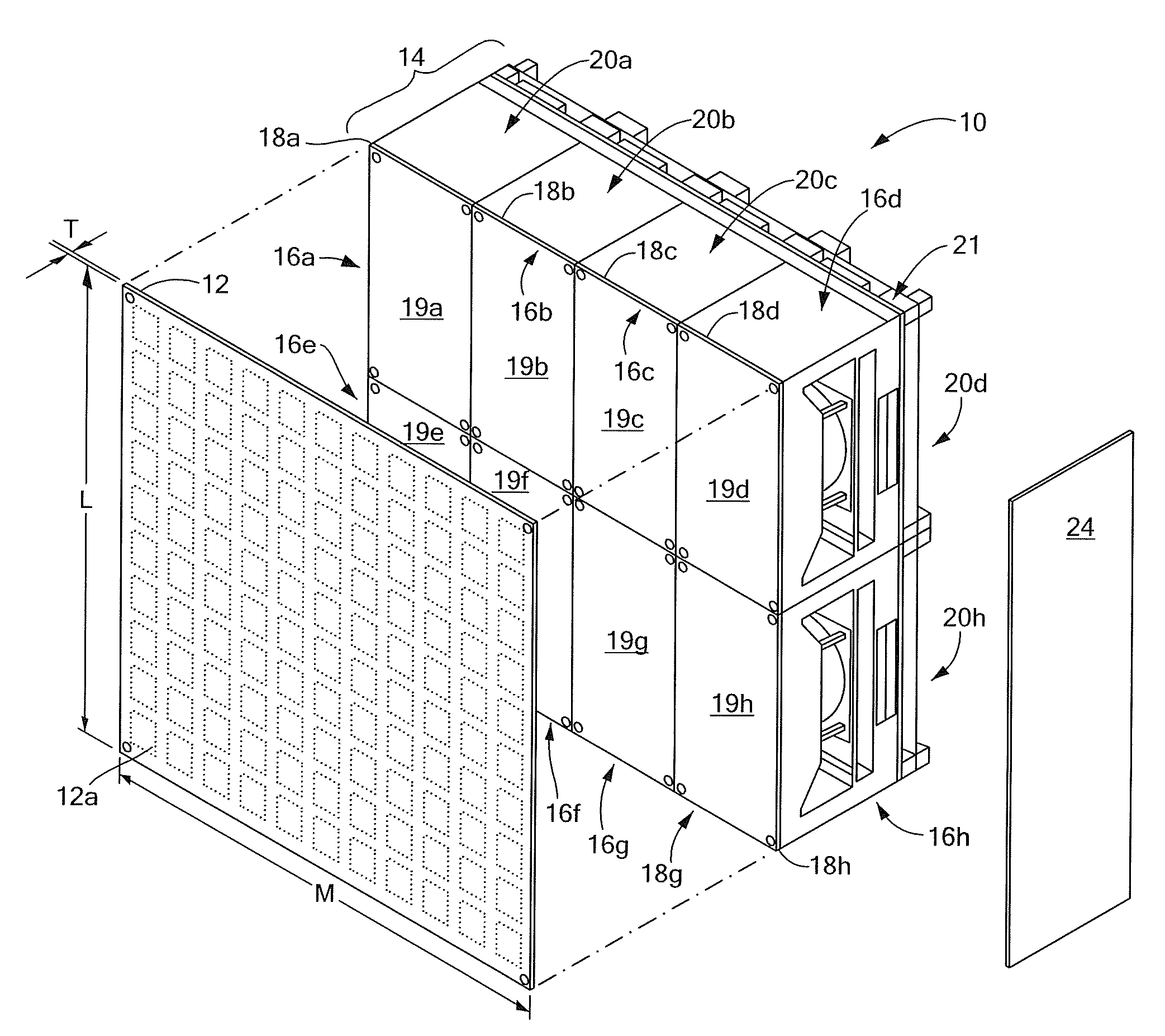
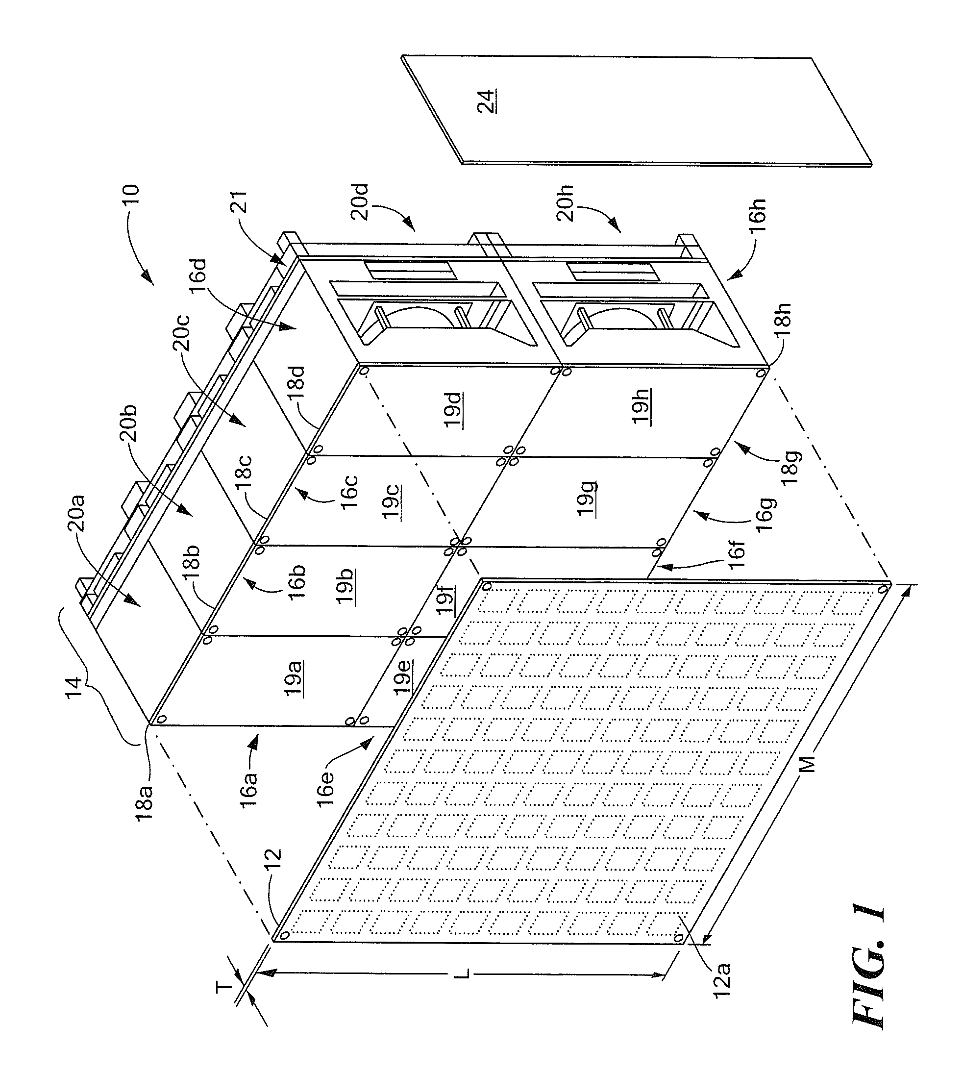
[0040]Referring now to FIG. 1, an exemplary active, electronically scanned array (AESA) 10 having a panel architecture is provided from an antenna panel 12 (also sometimes referred to herein as a “radiator panel”) coupled to an integrated panel array assembly (IPAA) 14. Antenna panel 12 is thin and generally planar and has a plurality of antenna elements generally denoted 13, disposed to transmit and receive RF energy through a first surface 12a thereof. Antenna elements 13 are shown in phantom since they are typically below external surface 12a and thus not directly visible in FIG. 1.

[0041]In one embodiment, antennal panel 12 may be provided as a stacked patch antenna panel configured for operation in the X-band frequency range and having a thickness (T) in the range of about 0.1 inch to about 0.4 inch (with a thickness typically of about 0.2 inch being preferred) and having a width (W) of about 0.5 meters (m) and a length (L) of about 0.5 m with 1024 patch antenna elements (not al...


PUM


Abstract

A thermal management system includes an air duct assembly comprising a supply air duct having an air inlet opening, a return air duct having an air exit opening and a plurality of distribution air ducts configured to be in fluid communication with the air inlet opening of the supply air duct and with the air exit opening of the return air duct. A fan is disposed within the air duct assembly to direct air from the air inlet opening of the supply air duct through the supply air duct and out the air exit opening of the return air duct. The fan and supply duct are disposed to direct air over a first surface of a heat sink. A second opposing surface of the heat sink is disposed over and configured to be in thermal contact with a plurality of active circuits disposed on a first surface of a radio frequency (RF) multi-layer printing wiring board (PWB).

Description

RELATED APPLICATIONS[0001]This application claims the benefit under 35 U.S.C. §119(e) of provisional application No. 61 / 162,798 filed on Mar. 24, 2009 which application is incorporated herein by reference in its entirety.FIELD OF THE INVENTION[0002]The structures and techniques described herein relate to thermal management of radio frequency (RF) systems and more particularly to cooling RF phased arrays.BACKGROUND OF THE INVENTION[0003]As is known in the art, a phased array antenna includes a plurality of antenna elements spaced apart from each other by known distances. Each of the antenna elements are coupled through a plurality of phase shifter circuits, amplifier circuits and / or other circuits to either or both of a transmitter or receiver. In some cases, the phase shifter, amplifier circuits and other circuits (e.g. mixer circuits) are provided in a so-called transmit / receive (T / R) module and are considered to be part of the transmitter and / or receiver.[0004]The phase shifters, ...

Claims


Application Information

Patent Timeline
Patent Type & Authority Applications(United States)
IPC IPC(8): H01Q1/22H05K7/20F28D21/00
CPCH01Q1/02H05K7/20154H01Q21/061H01L2224/73204H01L2224/73253
Inventor PUZELLA, ANGELO M.LICCIARDELLO, JOSEPH A.PEREIRA, STEPHEN J.ELLSWORTH, JOSEPH R.
Owner RAYTHEON CO
Why Eureka
Try Eureka