
Display with overlayed electronic skin

Active Publication Date: 2010-09-30
KENT DISPLAY SYST
View PDF38 Cites 128 Cited by
  • Summary
  • Abstract
  • Description
  • Claims
  • Application Information

AI Technical Summary

Benefits of technology

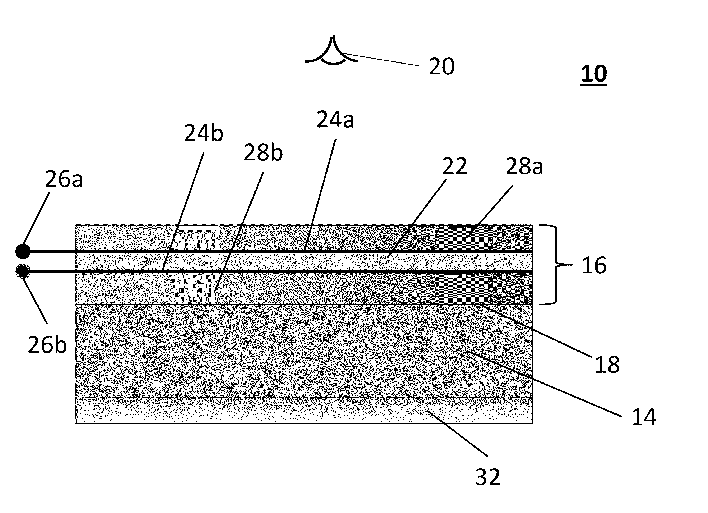
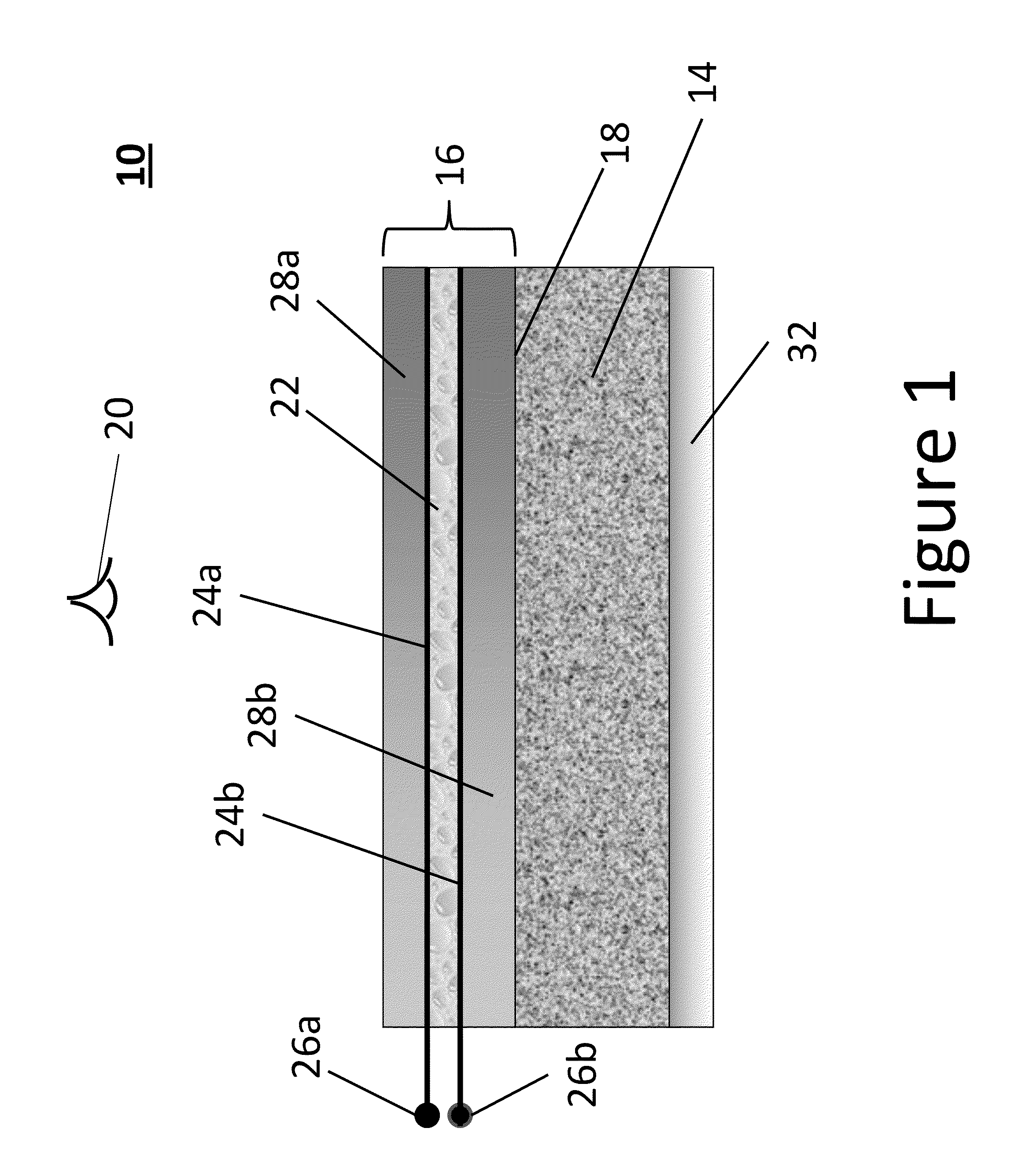
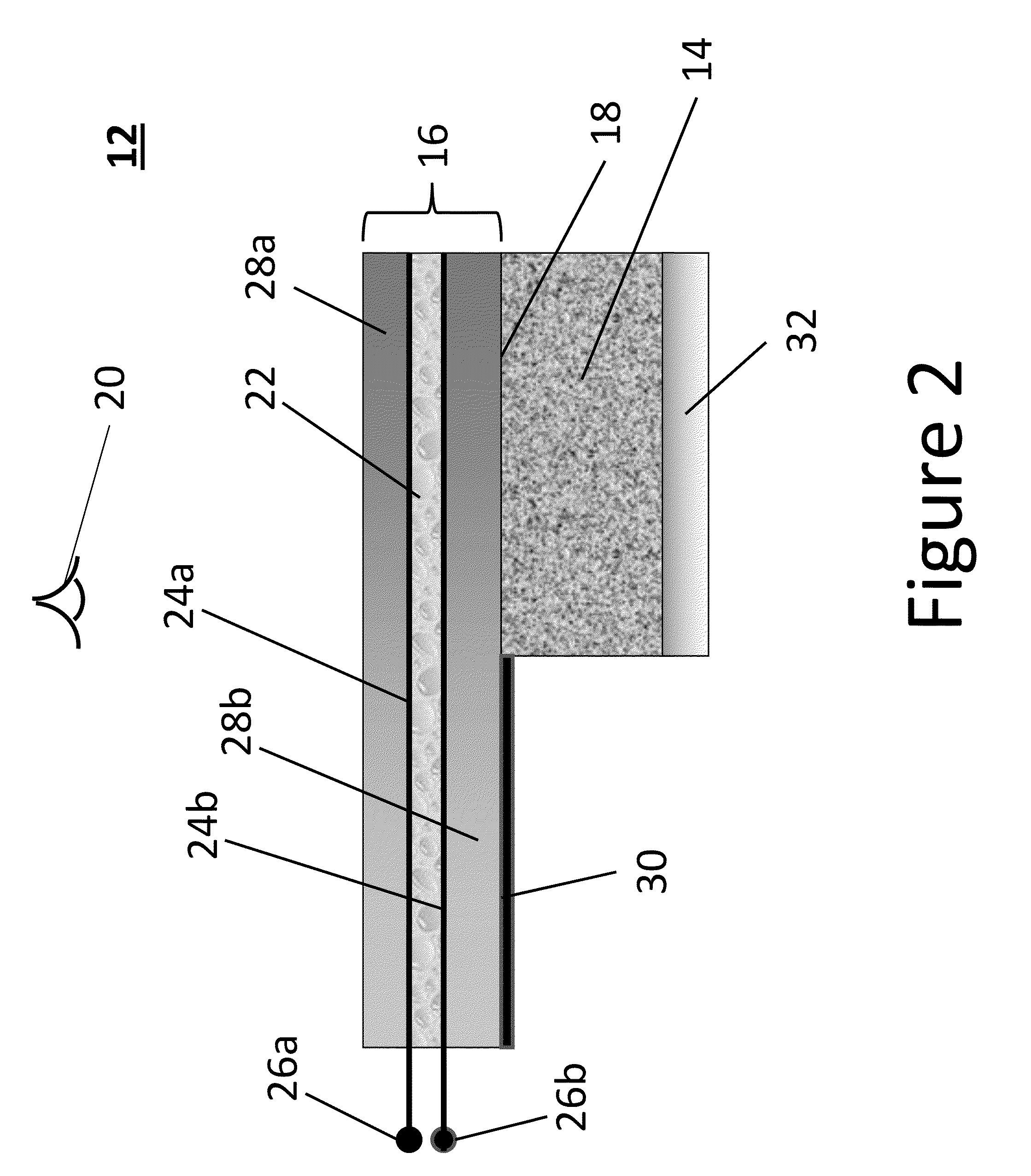
[0019]In one embodiment the skin is in the form of a writing tablet that covers all or a portion of the display. A transparent substrate or transparent, proximal polymer layer at a proximal location of the display forms a writing surface. The substrate or proximal polymer layer is flexible so as to be able to reduce a gap between the electrically conductive layers when writing pressure is applied to the writing surface. The electrically conductive layers are transparent. The circuitry can enable application of the voltages to the electrically conductive layers to erase the tablet or in some tablet designs while writing or selectively erasing where the pressure is locally applied to the tablet by a stylus of finger. The voltages enable the liquid crystal material to be placed into various states of reflectance including a reflective state and a substantially transparent state. Images or colors can be displayed on the tablet electronic skin while light passing through the electronic skin is absorbed by the display. When the display is bright, images can be displayed on the display that can be seen through the electronic skin although the display underneath will be more clearly visible when the tablet skin is erased or in the homeotropic texture.
[0021]The writing tablet can be used on mobile phones, digital cameras, and even desktop monitors where use is made of the black background of the display. The transparent tablet is optically coupled to conventional backlit displays with use of an index matching material. When the writing tablet is used, the display is darkened (e.g., turning OFF a backlit display or emissive elements) providing a black background. The transparent tablet can then be used to jot down notes, make art work, and doodle. The writing on the electronic skin may even stay on when the backlit display is in the bright state (e.g., turned ON in the case of a backlit display) since the contrast of the electronic skin will not be very high to substantially interfere with viewing images on the display.

Problems solved by technology

A problem with this technique is the relatively high cost and small color selection of covers.
The concept of electronically changing the color of a handheld or portable electronic device is not new and cell phone manufacturers have considered all available display technologies for this application.
Emissive displays such as these are not suitable technologies for electronic skins on cell phones since they draw substantial power from the cell phone battery and quickly drain it leaving little power available for the functional use of the cell phone or player.
However, many of them are not attractive for an electronic skin application because of many requirements: high reflectivity, wide color gamut, low cost, mechanical robustness, and thin conformable geometries in addition to low-power.
This technology, however, has insufficient color gamut and, even though bistable, is not a low power option in that it is current driven requiring significant power from the battery to change the color.
The bistable electrophoretic technology is used in black and white displays and covers but it is not yet developed for color.
Further, it is not attractive for conformable color electronic skin development as it would require high resolution patterning of the primary colors which adds considerably to the cost and limits the brightness to less than 33%.
Electromechanical displays also suffer from this 33% reflectance limitation.
Electrowetting lenses (U.S. Pat. No. 6,934,792) have been proposed; however, this scheme results in low reflectivity, the inability to mix colors, and suffers from objectionable layer thickness.
Polarizer-based LCD technologies (e.g., Zenthal Displays, bistable STN) have been made bistable for reduced power but these use color filters to achieve color and as such can suffer from not being reflective enough for electronic skin applications.
One major limitation of this technology for electronic skins is that power must be applied repetitively to display a particular color.
While the power drain is small compared to an emissive display, it nonetheless becomes quite significant and excessive on an area the size of an electronic skin since it must be applied continually or continually refreshed in order to maintain the selected color.
The color of the phone must be maintained even while the phone is not in operation, a serious problem for this technology.
Another serious problem is the complex cell structure further adds excessive cost in an electronic skin application.

Method used


Image

  • Display with overlayed electronic skin
  • Display with overlayed electronic skin
  • Display with overlayed electronic skin

Examples


example 1

Decorative Electronic Skin Example 1

[0061]A transparent electronic skin display was fabricated comprised of a triple stack of bistable polymer dispersed cholesteric liquid crystal layers as in FIG. 3. The layers were ordered such that the upper layer (closest to viewer) reflects red light; the middle layer reflects green light and the lower layer reflects blue light. The skin was made using 2 mil PET substrates each with an approximate area of 2×2 in2. Transparent conducting films using conducting polymer PEDOT were coated on the substrates. Bistable cholesteric liquid crystal dispersions were made using polymerization induced phase separation (PIPS) procedure as described in U.S. Pat. No. 7,351,506. Pre-polymerized liquid mixtures were mixed with 4.0 μm spacers for lamination between substrates. The single layer was first prepared using cholesteric liquid crystal reflecting at 640 nm. A small amount of the material was placed on one substrate. A second substrate was then laminated ...


PUM

PropertyMeasurementUnit
Lengthaaaaaaaaaa
Pressureaaaaaaaaaa
Electrical conductivityaaaaaaaaaa

Abstract

This disclosure features an electronic display with overlayed electronic skin. The display includes an outer transparent display surface and can be placed in a dark state or in a bright state. The skin overlays the outer display surface and includes an electro-optic layer. Transparent electrically conductive layers are disposed on each side of the electro-optic layer. Electronic circuitry applies voltages to the electrically conductive layers enabling the electro-optic material of the electronic skin to be placed into a substantially transparent state and a reflective state. Images or colors can be displayed on the electronic skin while portions of the electronic skin are in the reflective state and light passing through the electronic skin is absorbed by the display in the dark state. When the display is in the bright state images or colors can be displayed on the display that can be seen through the electronic skin.

Description

CROSS-REFERENCE TO RELATED APPLICATION[0001]This application claims the benefit of U.S. Provisional Patent Application Ser. No. 61 / 164,659 filed on Mar. 30, 2009, the contents of which are incorporated herein by reference in their entirety.TECHNICAL FIELD[0002]The technical field relates to display devices and to electronic skin affixed to the devices.BACKGROUND[0003]In order to satisfy the cell phone customer's desire for personal customization, the handset market offers a variety of different means of customization. Some handset manufactures sell phones in several colors. Such marketing requires the cell phone user to select the color of the phone during the sell process with no flexibility to change during the contract period. Other manufacturers offer replacement covers to the most popular types of phones. This solution meets the need for customization on one hand and the need to adopt and change color during the ownership period. Yet another customization option is the use of c...

Claims


Application Information

Patent Timeline
IPC IPC(8): G09G3/36
CPCG02F1/13476G02F2001/13332G02F2001/13478G06F3/041G06F1/1626G06F1/1643G02F2001/13775G02F1/13332G02F1/13478G02F1/13775
Inventor KHAN, ASAD
Owner KENT DISPLAY SYST
Learn More