

Projector
a projector and projector technology, applied in the field of projectors, can solve the problems of reducing optical reliability, preventing the reduction of projected image quality, and reducing optical reliability, and achieve the effect of excellent production efficiency and stable optical characteristics
- Summary
- Abstract
- Description
- Claims
- Application Information
AI Technical Summary
Benefits of technology
Problems solved by technology
Method used
Image

Examples
embodiment 1
[0031]A projector according to Embodiment 1 has a polarizing member that is disposed on the light exit side of a liquid crystal device. The polarizing member has in order light-transmissive substrate, a pressure-sensitive adhesive layer, a KE polarizer, an adhesive layer, and a support layer, and is positioned so that the adhesive layer is closer to the light exit side than is the KE polarizer.
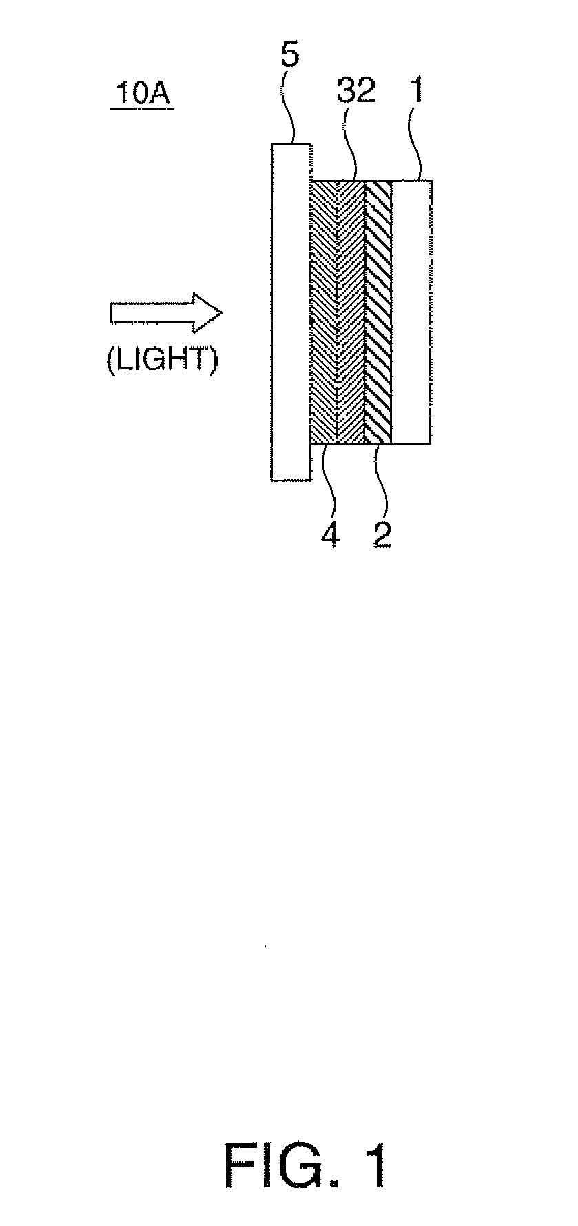
[0032]FIG. 1 shows a sectional view of the layer structure of a polarizing member 10A of the projector according to Embodiment 1.
[0033]In FIG. 1, 1 is a support layer, 2 is an adhesive layer, 3 is a KE polarizer, 4 is a pressure-sensitive adhesive layer, and 5 is a light-transmissive substrate.
[0034]Hereinafter, for convenience, all support layers are indicated by 1, all adhesive layers are indicated by 2, all pressure-sensitive adhesive layers are indicated by 4, and all light-transmissive substrates are indicated by 5.
Support Layer
[0035]The support layer 1 of the polarizing member 10A shown ...
embodiment 2
[0120]A projector according to Embodiment 2 is characterized in that a KE polarizer having a relatively large cross transmittance (Tc) is on the light incidence side (liquid crystal device), while a KE polarizer having a relatively small cross transmittance (Tc) is on the light exit side (projection optical system).
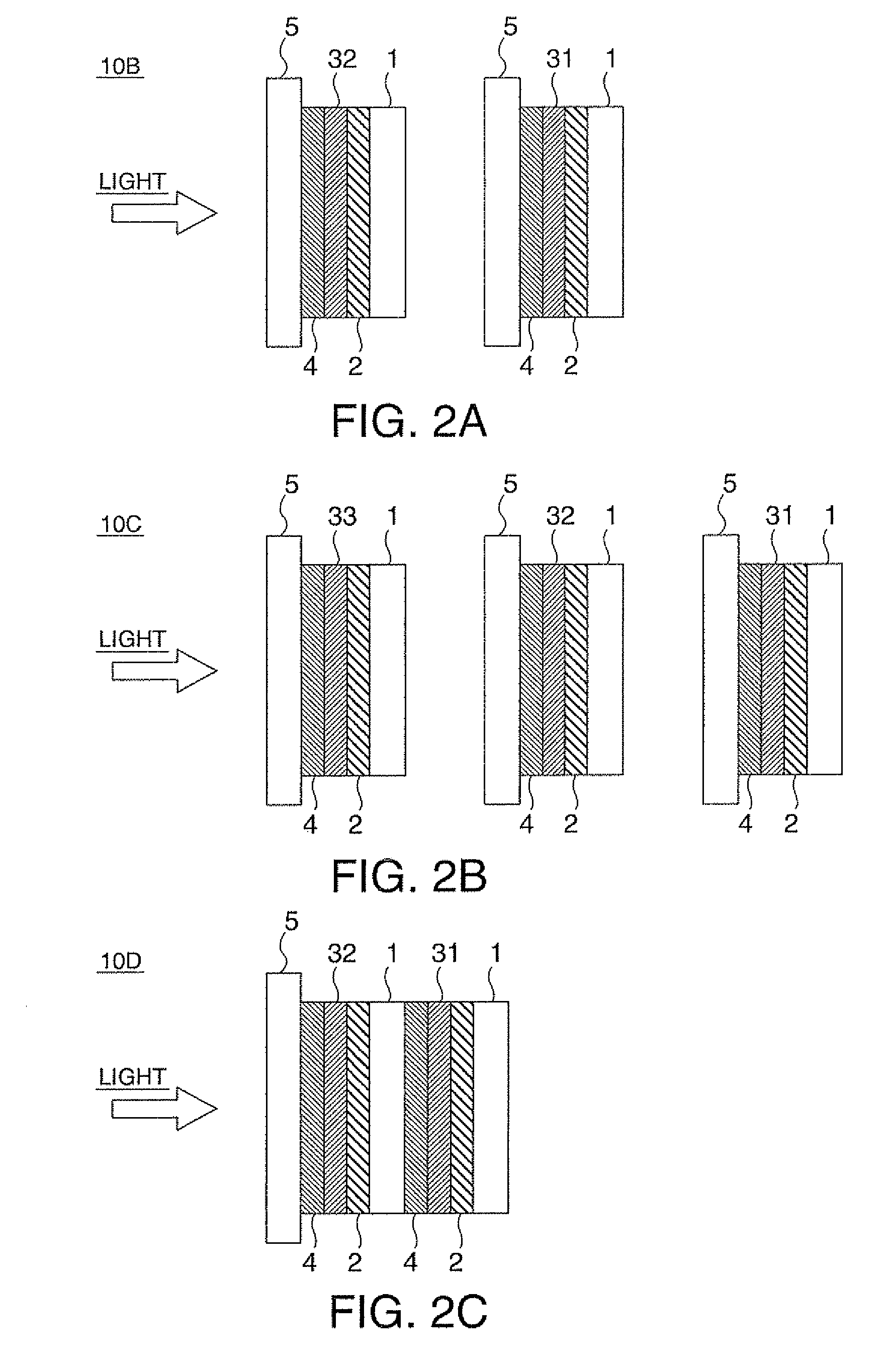
[0121]The projector according to Embodiment 2 may be a projector having a polarizing member that includes two KE polarizing elements: a KE polarizer (I) having a cross transmittance (Tc) of 0% to 0.1% and a KE polarizer (II) having a cross transmittance (Tc) of 45 to 55%. The projector according to Embodiment 2 may also be a projector having a polarizing member that includes three KE polarizers: a KE polarizer (I) having a cross transmittance (Tc) of 0% to 0.1%, a KE polarizer (II) having a cross transmittance (Tc) of 45 to 55%, and a KE polarizer (III) having a cross transmittance (Tc) of 61 to 71%.
[0122]FIGS. 2A and 2B show sectional views of polarizing members 10B and ...
embodiment 3
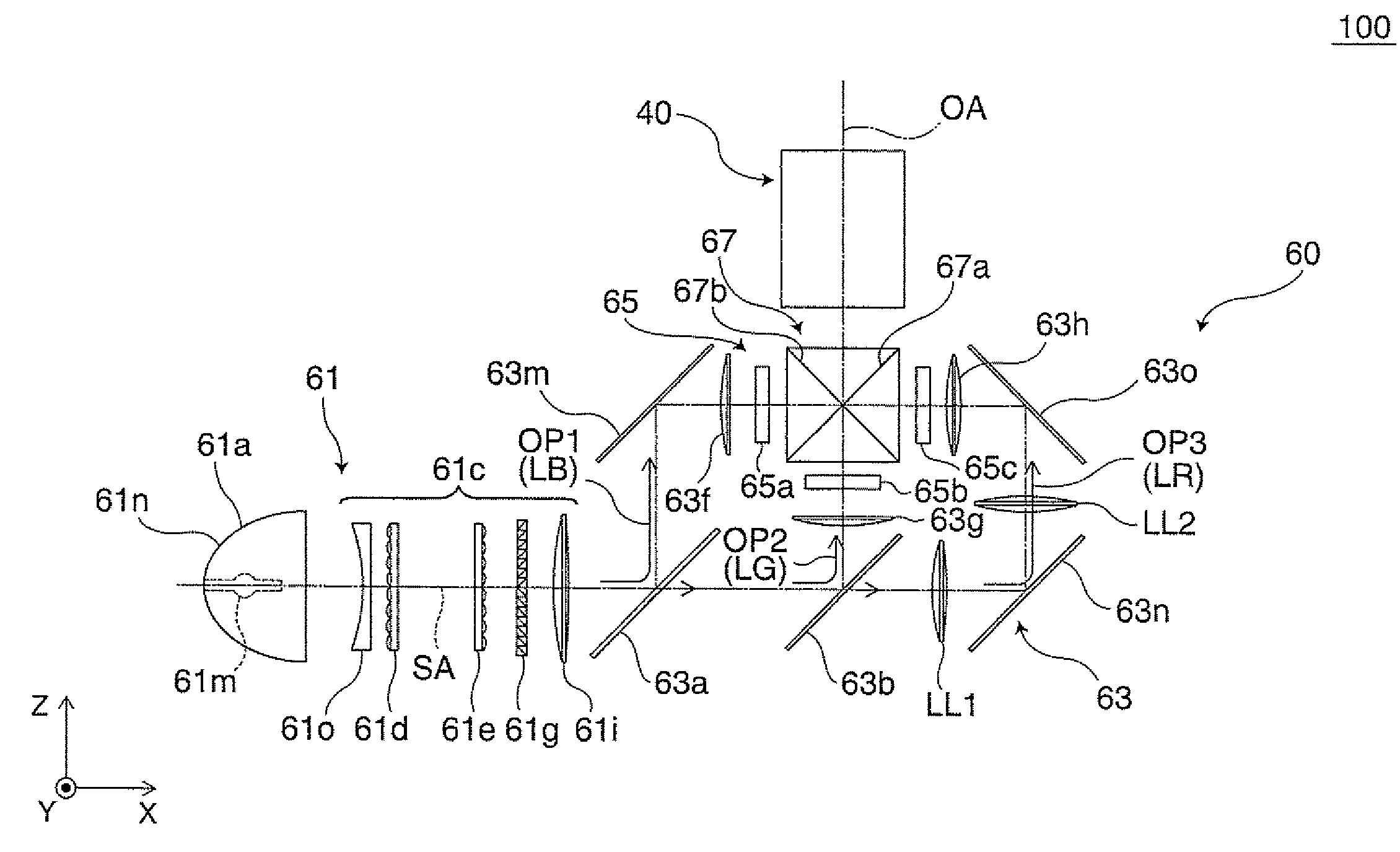
[0142]A projector according to Embodiment 3 is a projector having the liquid crystal devices 65a, 65b, and 65c of the projector 100 shown in FIG. 3. Each crystal device herein is an image-forming element having a liquid crystal panel sandwiched between a pair of polarizing plates as shown in FIG. 4.
[0143]In FIG. 4, 1 is a support layer, 2 is an adhesive layer, 31a and 31b are KE polarizers, 4 is a pressure-sensitive adhesive layer, 5 is a light-transmissive substrate, 6 is a liquid crystal panel, 20A is a polarizing member (incidence-side), and 10E is a polarizing member (exit side).
[0144]In each of the liquid crystal devices 65a, 65b, and 65c, the polarizing member 10E includes the support layer 1, the adhesive layer 2, the KE polarizer 31b, the pressure-sensitive adhesive layer 4, and the light-transmissive substrate 5, and is positioned so that the adhesive layer 2 is on the exit side and the KE polarizer 31b is on the incidence-side.
[0145]The cross dichroic prism 67 includes dic...
PUM
 Abstract
Description
Claims
Application Information