Poly-phase ac/dc active power converter

a technology of ac/dc active power converter and polyphase, which is applied in the direction of power conversion systems, instruments, climate sustainability, etc., can solve the problems of unavoidable power factor shift, undesirable harmonic distortion level, and contribute to the power supply additional weight, size and cos

Active Publication Date: 2010-09-30
AMETEK INC
View PDF3 Cites 30 Cited by
  • Summary
  • Abstract
  • Description
  • Claims
  • Application Information

AI Technical Summary

Benefits of technology

[0008]It is another aspect of the present invention to provide a poly-phase AC / DC active power converter to convert AC power from a poly-phase variable frequency power source into DC power, comprising an H-bridge converter maintaining a capacitor at its output, the converter adapted to receive each of the phases of AC power source at its input through respective line reactors inline therewith, a controller coupled to the H-bridge converter to control the converter in accordance with a control structure, wherein upon the initial powering of the H-bridge, the controller enters a voltage boost mode, such that the line reactors are charged and discharged into the capacitor to raise its voltage above that of the power source, to generate a gain value used by the control structure to control the current consumed from the power source, so as to maintain a constant output voltage during the start up of a normal AC / DC conversion mode, so as to reduce an inrush of current during the conversion of AC power into DC power.

Problems solved by technology

Unfortunately, the components that are to be powered in many applications are designed to operate within narrow bands of incoming line frequency and voltages.
However, the rectification of the incoming AC power by the transformer may result in uncorrected and unavoidable power factor shifts, while injecting an undesirable level of harmonic distortion back onto the power grid.
Because the performance of such transformer designs tends to be dependent on phase voltage balance, line reactors are required to smooth and balance the capacitor charging currents supplied by the poly-phase transformer, which contributes additional weight, size, and cost to the power supply.
Thus, while existing transformer designs provide adequate performance, they are deficient with regard to their large size, significant weight, and excessive cost, and do not compensate for load power factor, thus rendering power converters using such transformers undesirable.
However, upon start up of the converter, the lack of voltage potential between the incoming mains and the DC bus, to which the converter is coupled, compromises control loop stability due to the lack of a forcing function (voltage difference) to provide the required gain for the control loop to correctly operate.
This can result in initial startup currents that are largely uncontrolled, which places a significant amount of electrical stress on the components of the power converter and the power grid, resulting in a reduction in their operational reliability.
Thus, while active power converters can provide power factor correction in a reduced form factor, that is lightweight, they can suffer from startup current spikes, undesirable even-harmonic line distortion, and errors as the operating frequency of the mains power source changes.
While the synchronization established by the PLL mitigates any cumulative error, errors during each cycle of the input line power still occur.
Thus, while PLLs generally provide acceptable performance under steady state conditions, they can produce significant errors during transient conditions when the frequency of the input line power is changing, which frequently occurs, when a variable frequency power source is used to supply power to the converter.

Method used


Image

  • Poly-phase ac/dc active power converter
  • Poly-phase ac/dc active power converter
  • Poly-phase ac/dc active power converter

Examples


Embodiment Construction

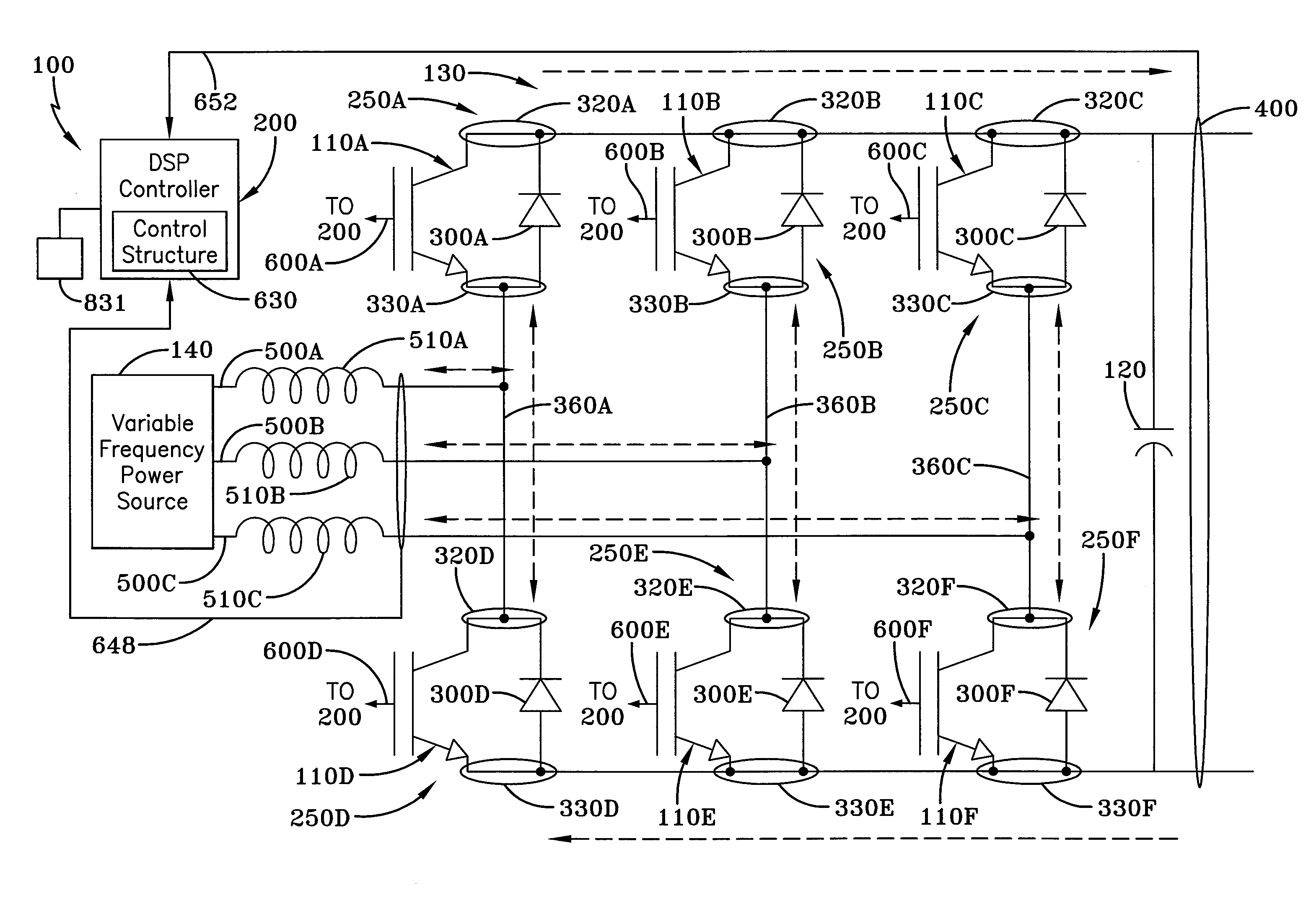
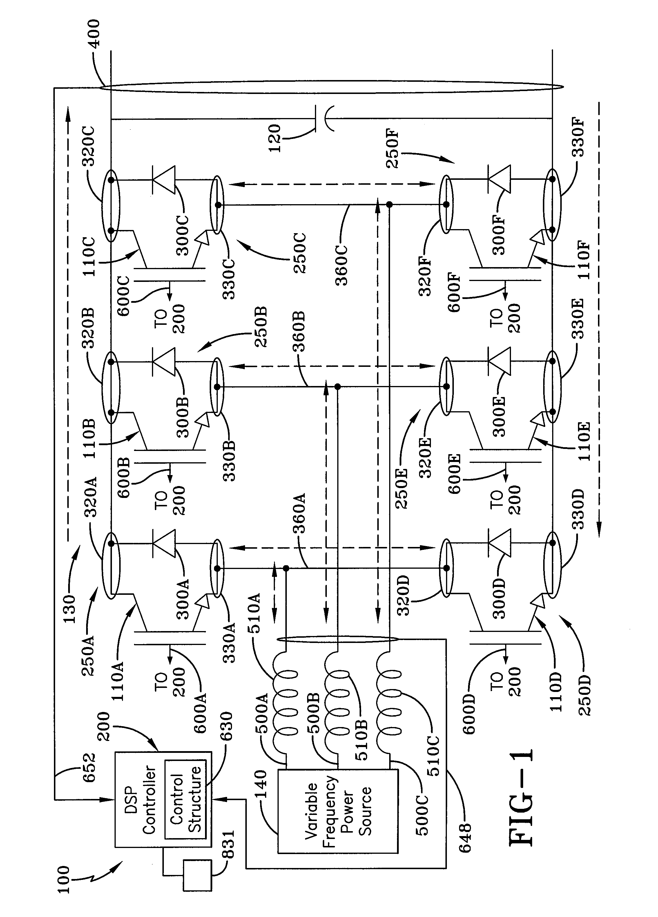
[0019]A poly-phase AC / DC active power converter is generally referred to by the numeral 100, as indicated in FIG. 1 of the drawings. The power converter 100 utilizes a plurality of insulated-gate bipolar transistors (IGBT) 110A-F and a DC-link capacitor 120 configured as a three-phase active H-bridge 130 to convert AC (alternating current) power received from a three-phase variable frequency power source 140, which generates power at varying frequencies, into DC (direct current) power. To reduce the inrush of electrical current into the converter 100 upon a cold start, or initial operation, of the converter 100, where the DC-link capacitor voltage is zero, a DSP (digital signal processing) controller 200 follows a control structure, which controls the IGBTs 110A-F in a predetermined sequence, to reconfigure the H-bridge 130 to operate in a boost regulation mode.

[0020]In the boost regulation mode, the converter 100 operates as a boost rectifier, such that the voltage at the DC-link c...


PUM


Abstract

A three-phase AC / DC active power converter provides an H-bridge that is controlled by a DSP (digital signal processing) controller that places the H-bridge in a voltage-boost mode of operation when voltage of a DC-link capacitor maintained by the H-bridge is near than the voltage input from a three-phase power source. The voltage difference between the boosted DC-link voltage and the three-phase power source voltage provides a voltage potential thereby giving the control loops a possible gain value. The gain value provides loop stability to thereby prevent an inrush of electrical current into the power converter upon startup. The converter also allows harmonic distortion to be modified through wave shaping of the normally pure sinus conduction signal.

Description

TECHNICAL FIELD[0001]The present invention is generally directed to AC / DC active power converters. Particularly, the present invention relates to a poly-phase AC / DC active power converter for use with a variable frequency generator. More particularly, the present invention is directed to an AC / DC active power converter that is reconfigured on start-up to operate in a voltage boost mode to generate a gain voltage to reduce electrical current spikes otherwise seen by the power converter. Additionally, the present invention is directed to an AC / DC active power converter that utilizes real-time geometric calculations to identify the conduction phase angle of the input power, so as to output power having a unity power factor.BACKGROUND ART[0002]Electrical generation systems often provide power consumed by power converters, such as three-phase AC / DC or AC / AC power converters. These power converters modify incoming AC (alternating current) power so that it is output with different electric...

Claims


Application Information

Patent Timeline
Patent Type & Authority Applications(United States)
IPC IPC(8): H02M7/162
CPCH02M1/4225Y02B70/126H02M7/1626Y02B70/10
Inventor KAZLAUSKAS, WILLIAM J.
Owner AMETEK INC
Why Eureka
Try Eureka