Anti-fuse element

a technology of anti-fuse elements and circuits, applied in static storage, electrical equipment, instruments, etc., can solve the problems of not keeping its programmatic state throughout its lifetime, specific technology is not easily available, and cannot be programmed outside the process flow

Active Publication Date: 2010-09-30
NXP USA INC +1
View PDF11 Cites 55 Cited by
  • Summary
  • Abstract
  • Description
  • Claims
  • Application Information

AI Technical Summary

Benefits of technology

[0019]According to an embodiment of the present invention, the method further comprises, prior to applying said programming voltage, applying a soft programming voltage at said first node, said soft programming voltage being at one of two levels to simulate the effect of hard programming of said anti-fuse cell without causing break-down of said first and second anti-fuse devices.

Problems solved by technology

A drawback of this type of fuse is that it is unreliable, meaning that it may not keep its programmed state throughout its lifetime.
A drawback of this solution is that a high voltage is required to break-down the dielectric, higher than the normal voltages used on the integrated circuit, and thus requires specific technology adapted to function at the higher voltages.
In many semiconductor technologies, such specific technology is not easily available.
A drawback of such a fuse is that it cannot be programmed outside the process flow, in other words in the final application.
A further drawback of the above solutions is the chip area they consume, and their power consumption which is relatively high.

Method used


Image

  • Anti-fuse element
  • Anti-fuse element
  • Anti-fuse element

Examples


Embodiment Construction

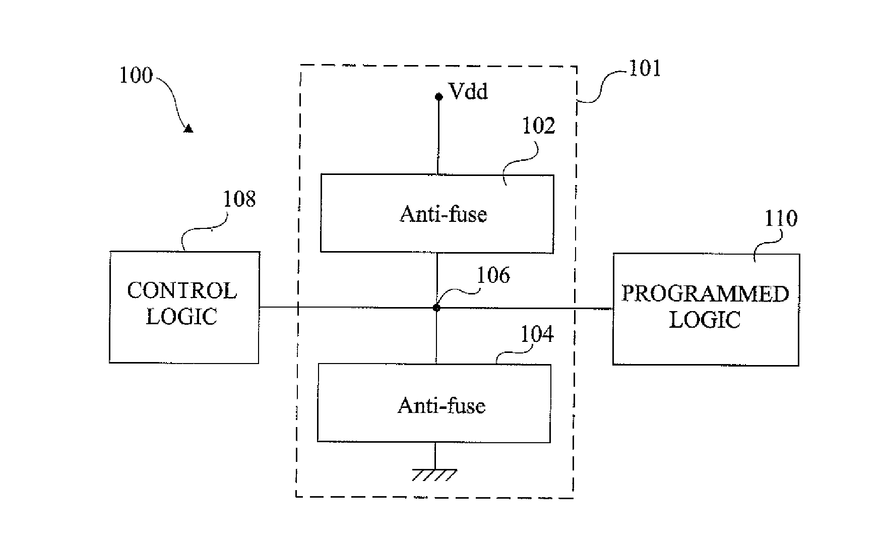
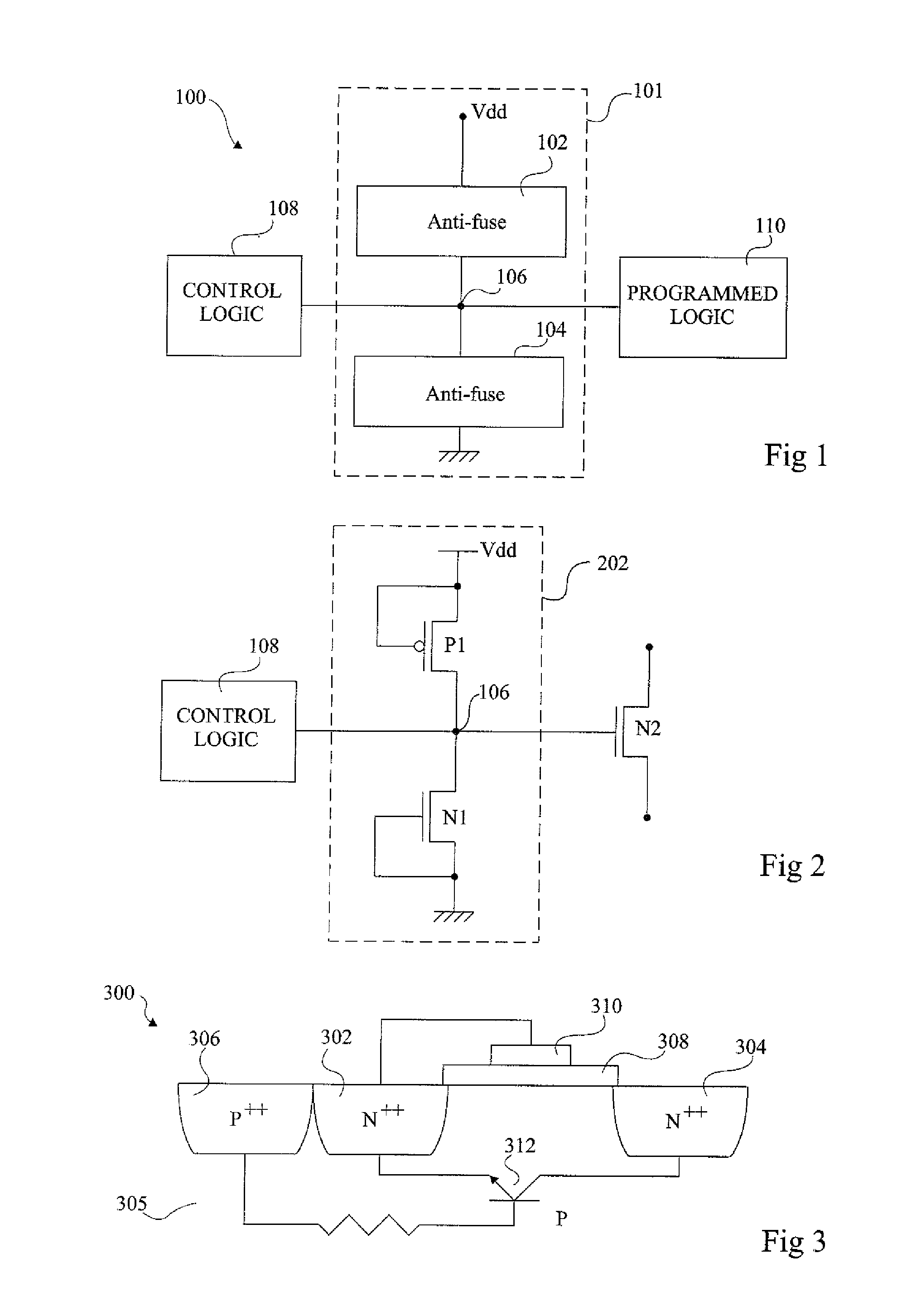
[0028]FIG. 1 illustrates anti-fuse circuitry 100, comprising an anti-fuse cell 101 comprising a pair of anti-fuses 102 and 104. Anti-fuse 102 is coupled between a supply voltage Vdd and a node 106, while anti-fuse 104 is coupled between node 106 and ground. Node 106 is also coupled to control logic 108, which programs the anti-fuses 102 and 104. Node 106 is further coupled to programmed logic 110, which is, for example, in any circuitry arranged to act in response to the states of the anti-fuses 102 and 104.

[0029]Anti-fuses 102 and 104 are each open prior to programming, in other words isolating node 106 from the supply voltage Vdd and from ground. During a programming phase, one or the other of the anti-fuses 102, 104 is broken-down, such that node 106 is coupled to either the supply voltage Vdd or to ground. To achieve this, control logic 108 applies a programming voltage to node 106. Anti-fuses 102 and 104 do not require high voltages to cause break-down as break-down is for exam...


PUM


Abstract

Programmable anti-fuse circuitry including at least one anti-fuse cell having a first anti-fuse device coupled between a supply voltage and a first node and a second anti-fuse device coupled between the first node and a ground voltage, and control logic coupled to the first node and arranged to generate a programming voltage having one of at least a first voltage level for breaking-down the first anti-fuse device but not the second anti-fuse device and coupling the first node to the supply voltage; and a second voltage level for breaking-down the second anti-fuse device but not the first anti-fuse device and coupling the first node to the ground voltage.

Description

CROSS REFERENCE TO RELATED APPLICATIONS[0001]This application is a U.S. national stage patent application based on PCT application number PCT / IB2007 / 055366, entitled “Anti-Fuse Element”, filed on Oct. 3, 2007 which application is hereby incorporated by reference to the maximum extent allowable by law.BACKGROUND OF THE INVENTION[0002]1. Field of the Invention[0003]The present invention relates to anti-fuse circuitry, and in particular to programmable voltage controlled anti-fuse circuitry.[0004]2. Background of the Invention[0005]Fuses and anti-fuses are used in multiple applications to allow internal connections on an integrated circuit to be modified after the process flow has been completed. Such fuses may be programmed by a programming signal to change the state of the connection between two points. Whereas a fuse is a switch which is normally closed, and can be opened by programming such that no current flows through the fuse, an anti-fuse is a switch which is normally open, and...

Claims


Application Information

Patent Timeline
Patent Type & Authority Applications(United States)
IPC IPC(8): G11C17/00H01H37/76
CPCG11C17/18G11C17/16
Inventor BOROT, BERTRANDZECRI, MICHEL
Owner NXP USA INC
Why Eureka
Try Eureka