
Image forming apparatus and image forming method

Inactive Publication Date: 2010-09-30
SEIKO EPSON CORP
View PDF6 Cites 2 Cited by
  • Summary
  • Abstract
  • Description
  • Claims
  • Application Information

AI Technical Summary

Benefits of technology

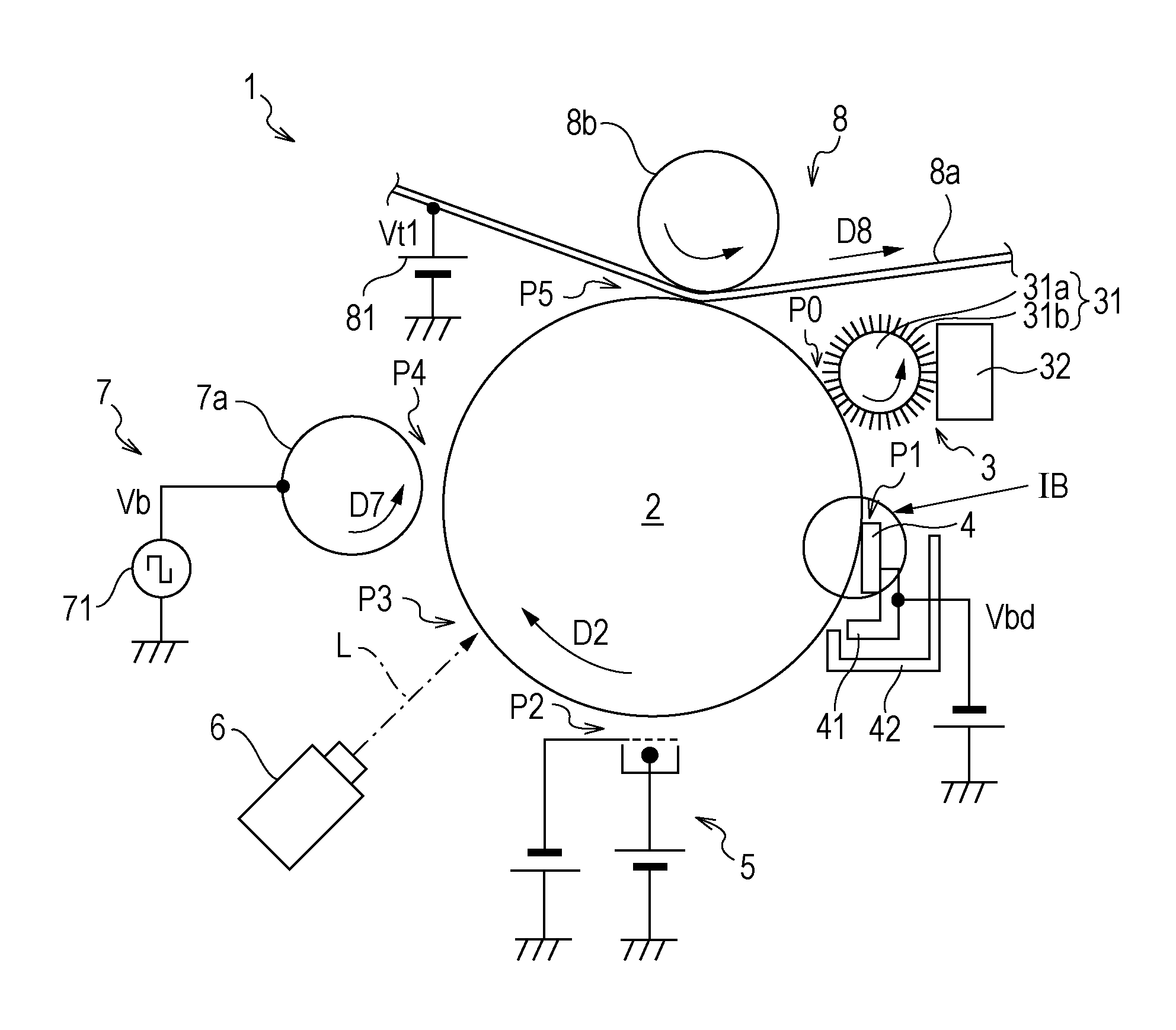
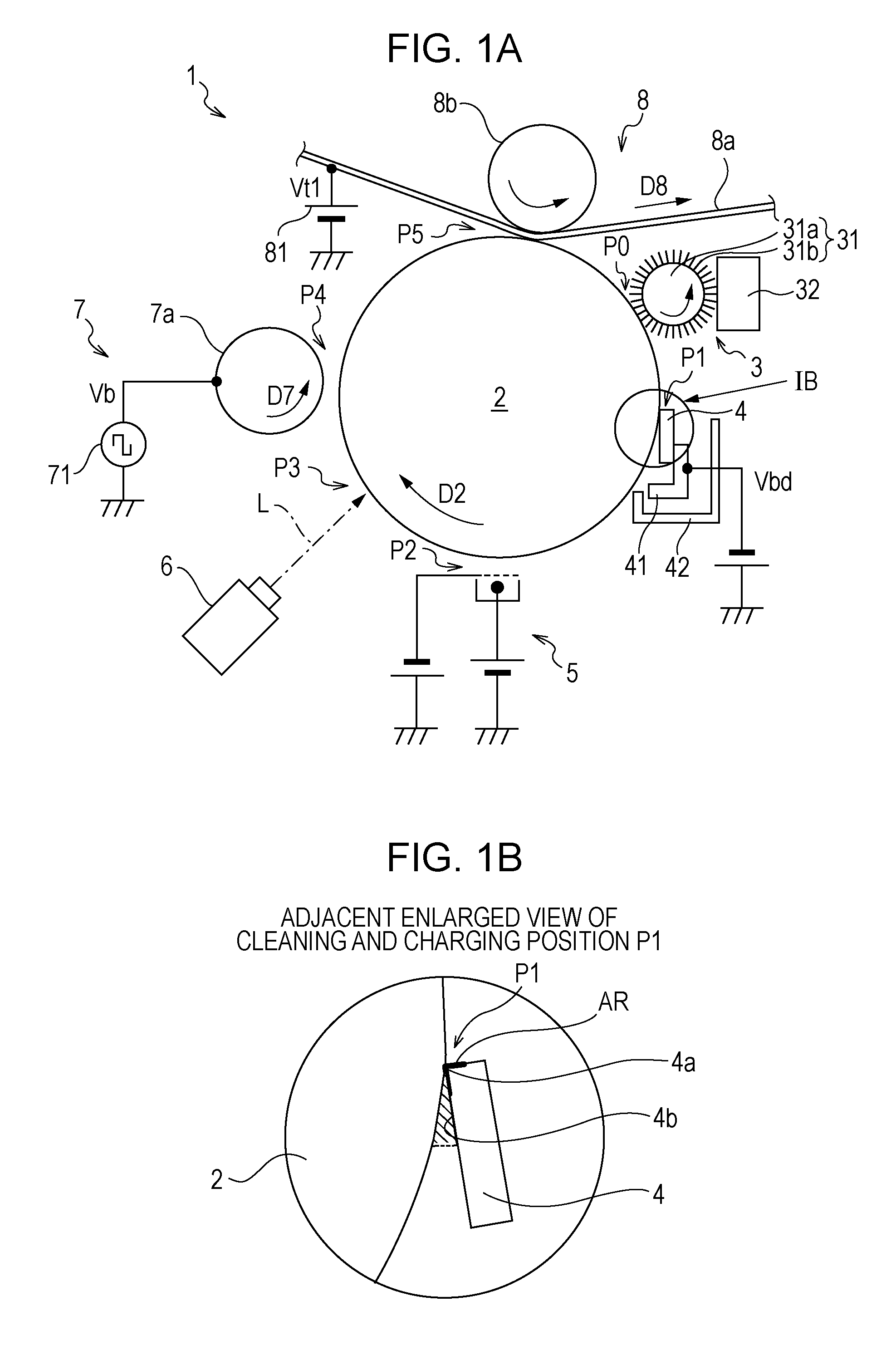
[0008]An advantage of some aspects of the invention is that it provides an image forming apparatus and an image forming method in which a charging process and a cleaning process on a surface of a latent image carrier can be desirably performed with a small number of components.
[0012]In addition, if the toner is adhered to a ridge line portion in which the conductive blade is in contact with the latent image carrier, a charging characteristic or cleaning ability is deteriorated. Moreover, in the invention, since the lubricant is applied to the surface of the latent image carrier, adherence of the toner to the ridge line portion tends to be increased by the lubricant. However, since the toner includes the additive having the abrasion effect, the toner or lubricant adhered to the ridge line portion of the conductive blade is abraded by the additive, thereby controlling increase of the adhered toner. Thus, it is possible to achieve a desired charging process and cleaning process of the surface of the latent image carrier over a long period of time. Herein, the additive having such an abrasion effect may employ, for example, strontium titanate.
[0015]Moreover, as an example of the two stages of charging, the surface of the latent image carrier may be charged at the first electric potential having the same polarity as the normal charged polarity according to application of direct current voltage having the same polarity as the normal charged polarity of the toner by the conductive blade, and then, electric charges having reverse polarity to the normal charged polarity may be provided by the charger to adjust the electric potential of the surface of the latent image carrier to the second electric potential. Thus, the surface of the latent image carrier can be more uniformly charged.
[0017]Moreover, the toner may include the additive having a leak function, thereby preventing reduction in the charging electric potential. That is, the charging in the cleaning and charging position becomes unstable while the cleaning and charging are repeated by the conductive blade, thereby causing problems such as reduction in the charging electric potential. However, if the toner includes the additive having the leak function, even though the toner is adhered to the conductive blade due to a long period of use, electric charges are provided to the surface of the latent image carrier through the leak additive, thereby desirably charging the surface of the latent image carrier. As a result, it is possible to achieve desirable image forming without a charging error over a long period of time. Titania, oxide semiconductor or inorganic particulates which are coated by a semiconductive film on at least part of a surface thereof may be used as the leak additive.

Problems solved by technology

This small particle diameter toner escapes from the cleaning blade, and thus, it is difficult to remove the remaining toner from the latent image carrier.
Further, a filming layer is gradually formed on the surface of the latent image carrier by the remaining toner, to thereby decrease the transfer efficiency and to increase a friction coefficient of the cleaning blade and the latent image carrier, thereby leading to problems such as damage to the latent image carrier.
Thus, even though the filming layer is prevented from being formed on the surface of the latent image carrier by using the above described lubricant, the toner is adhered on the front end part of the cleaning blade, and thus, the charging becomes unstable and image deterioration occurs due to the cleaning deterioration.
In addition, if the toner is adhered to a ridge line portion in which the conductive blade is in contact with the latent image carrier, a charging characteristic or cleaning ability is deteriorated.
That is, the charging in the cleaning and charging position becomes unstable while the cleaning and charging are repeated by the conductive blade, thereby causing problems such as reduction in the charging electric potential.
However, if the toner includes the additive having the leak function, even though the toner is adhered to the conductive blade due to a long period of use, electric charges are provided to the surface of the latent image carrier through the leak additive, thereby desirably charging the surface of the latent image carrier.

Method used


Image

  • Image forming apparatus and image forming method
  • Image forming apparatus and image forming method
  • Image forming apparatus and image forming method

Examples


Embodiment Construction

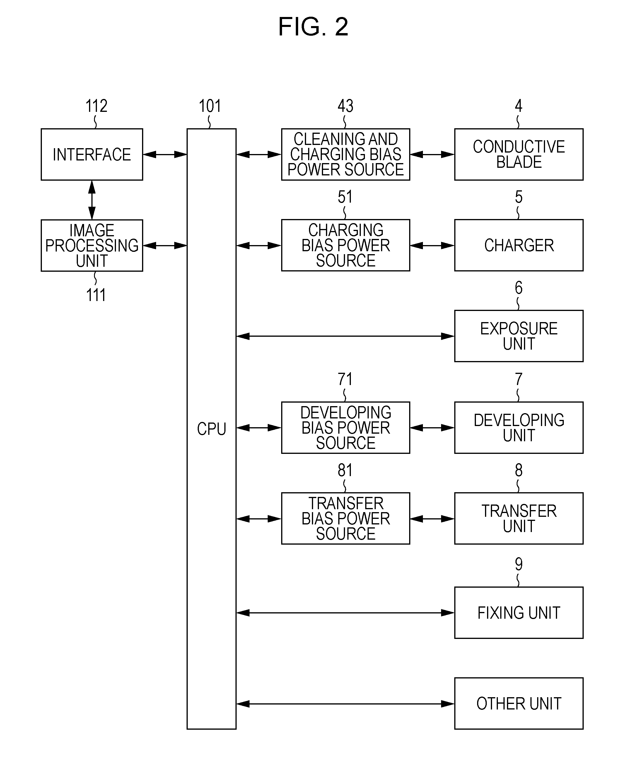
[0022]FIG. 1 schematically illustrates a main configuration of an embodiment of an image forming apparatus according to the invention. FIG. 2 is a block diagram illustrating an electric configuration of the apparatus in FIG. 1. In the image forming apparatus 1, an image is formed using a nonmagnetic one-component system negative charged toner. That is, in this embodiment, negative polarity is “normal charged polarity”. Alternatively, the image may be formed using a positive charged toner in which positive polarity is the normal charged polarity. Hereinafter, it is assumed that the image forming apparatus 1 uses a negative charged toner. However, in the case that the positive charged toner is used, a charging electric potential of each member to be described below may be set to reverse polarity. Herein, the toner includes a toner mother particle and an additive which is added to the toner mother particle, but in the following description, “toner” refers to all the particles made by a...


PUM


Abstract

An image forming apparatus includes: a latent image carrier which circumferentially rotates in a predetermined rotational direction; a lubricant applying unit which applies a lubricant on a surface of the latent image carrier in a predetermined application position; a developing unit which adheres a toner including an additive having an abrasion effect onto the surface of the latent image carrier on which the lubricant is coated to form a toner image, in a development position located on a downstream side of the application position in the rotational direction; and a conductive blade which cleans and removes the toner on the surface of the latent image carrier in contact with the surface of the latent image carrier, and charges the surface of the latent image carrier, in a cleaning and charging position located on an upstream side of the development position in the rotational direction.

Description

BACKGROUND[0001]1. Technical Field[0002]The present invention relates to an image forming apparatus and an image forming method in which a toner image is formed by developing an electrostatic latent image formed on a surface of a latent image carrier using a toner, and more specifically, to cleaning and charging the surface of the latent image carrier.[0003]2. Related Art[0004]An image forming apparatus and a method thereof are known in the related art, in which a toner image is formed by developing an electrostatic latent image formed on a surface of a latent image carrier which circumferentially rotates in a predetermined rotational direction using a toner, and is transferred to a transfer medium. In the image forming apparatus and the method thereof, since the efficiency of the transfer from the latent image carrier to the transfer medium is 100% or less, a small amount of toner may remain on the surface of the latent image carrier after transfer. In such an image forming apparat...

Claims


Application Information

Patent Timeline
IPC IPC(8): G03G21/10
CPCG03G2221/0005G03G21/0023G03G21/0017
Inventor MAEDA, MASAHIROYAMADA, YOICHIKOBASHI, MASARUARUGA, TOMOHIROFUKUMOTO, TAKATOMOKITAZAWA, ATSUNORI
Owner SEIKO EPSON CORP
Learn More