Supercharge Your Innovation With Domain-Expert AI Agents!

Fuel cell system and method for limiting current thereof

Active Publication Date: 2010-09-30
TOYOTA JIDOSHA KK
View PDF3 Cites 5 Cited by
  • Summary
  • Abstract
  • Description
  • Claims
  • Application Information

AI Technical Summary

Benefits of technology

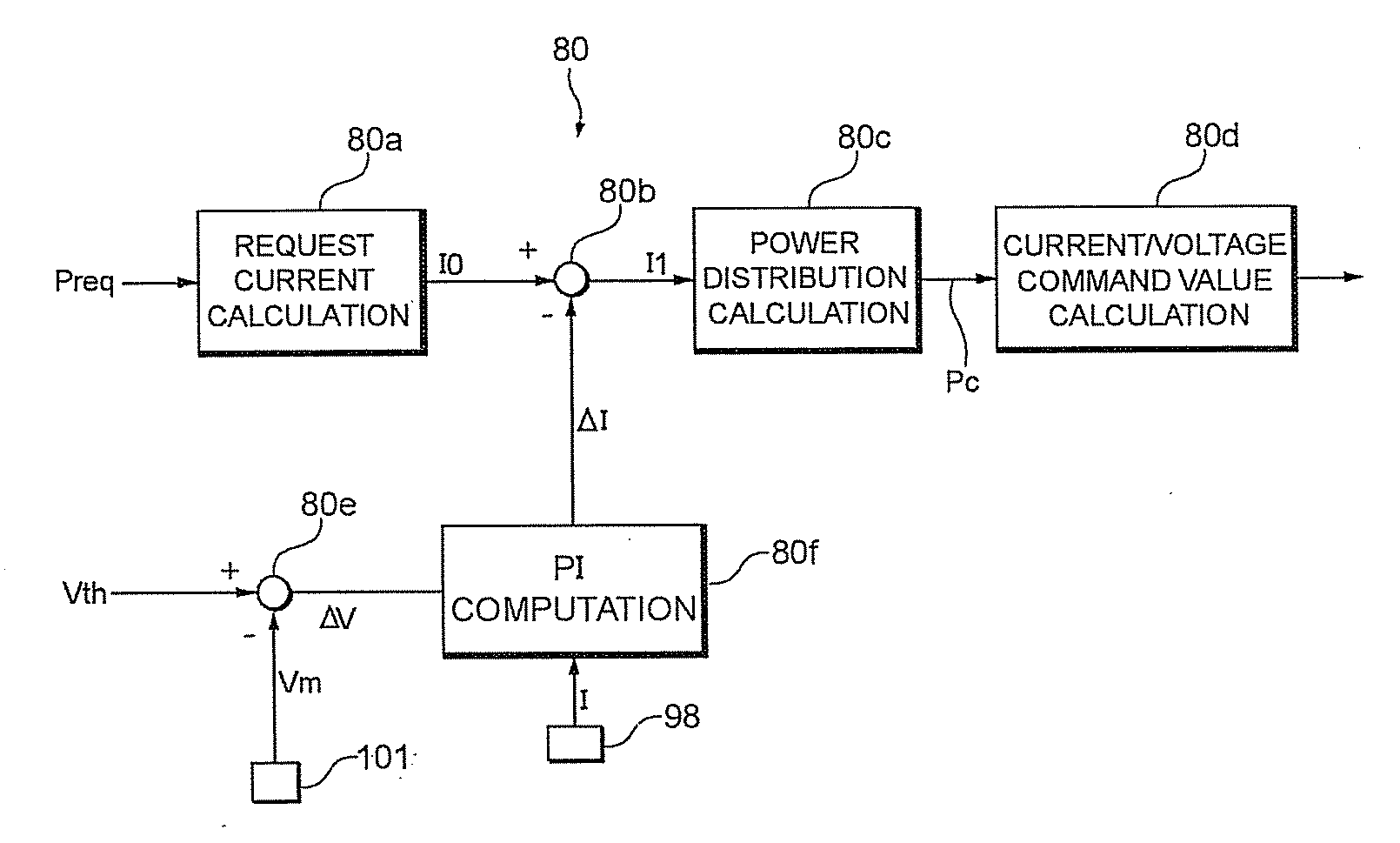
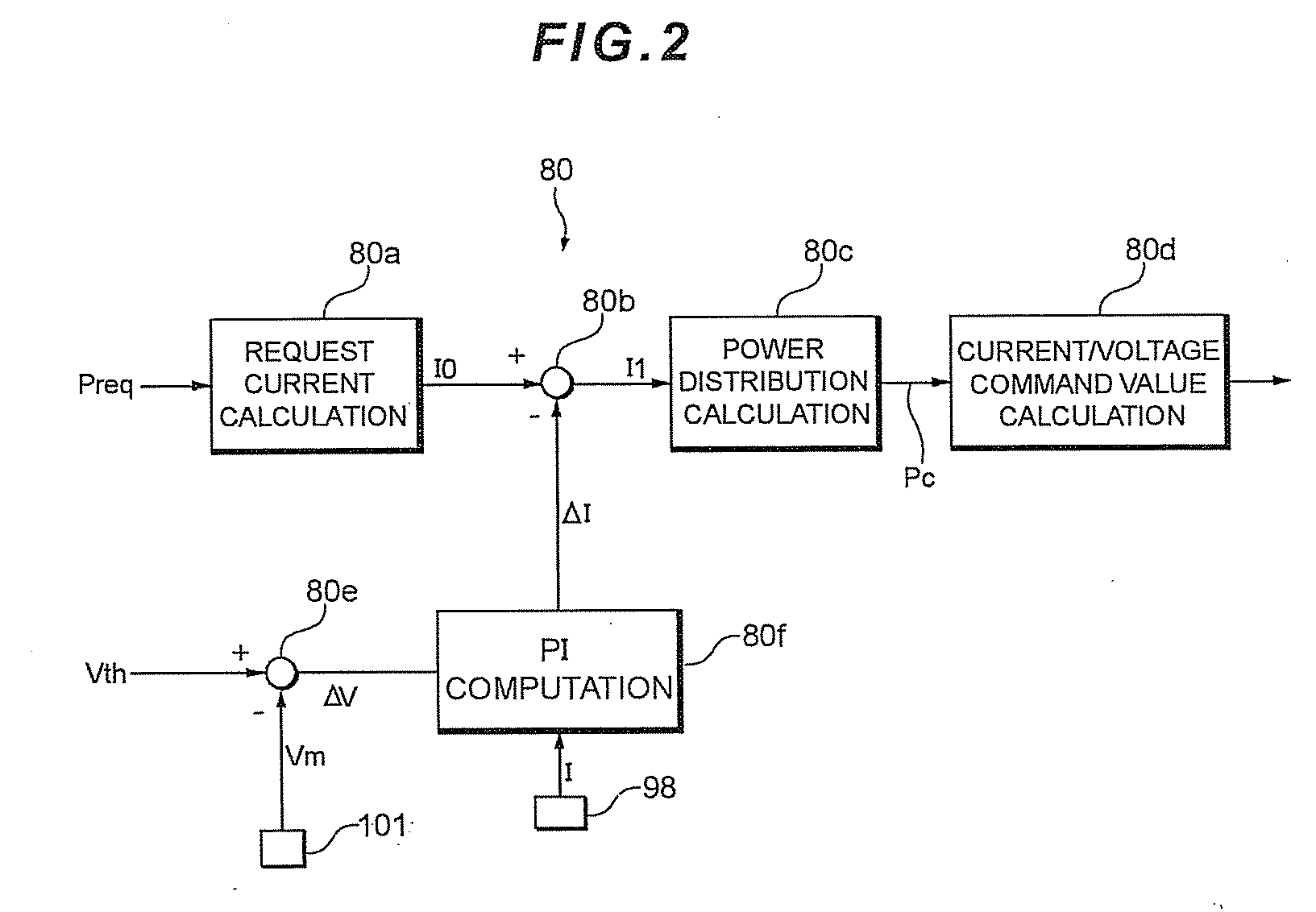
[0012]In light of the problems of the conventional techniques above, an object of the present invention is to provide a fuel cell system that enables a system-request current to be securely limited in any operation statuses, and also enables a supply current to be made rapidly responsive when the current is limited while enabling the supply current to be stably converged when the current is restored.

Problems solved by technology

In a situation where a fuel cell having a plurality of cells is used, when even only one of the plurality of cells becomes unable to generate electrical power, the entire fuel cell becomes unable to generate electrical power.
However, in conventional fuel cell systems, when electrical power to be generated by the fuel cell is controlled or a supply current to be supplied to a load is limited under certain conditions, a system-request power, being the reference for the limiting computation, in the fuel cell increases, and the fuel cell system might eventually become unable to perform limiting processing for the power to be generated or the supply power.
When the power to be generated or a supply power is limited, the driver feels as if a motor output is insufficient and performs an operation such as further stamping on an accelerator.
As a result of the increase in system-request power due to such an operation, the power to be generated or supply current also increases, and consequently necessary limiting processing becomes unable to be performed.
In other words, if one of cell voltages falls below a lowest-cell-voltage acceptable value, a current value of an actual supply current is limited.
At this time, the current limiting processing is required to rapidly limit a current; however since the current restoration processing has been controlled using the same response as in the current limiting processing, overshooting might occur in the supply current during the current restoration processing.
On the other hand, if the response that will not cause overshooting in the current restoration processing is set, it is expected that the response will be poor at current limiting processing.

Method used


Image

  • Fuel cell system and method for limiting current thereof
  • Fuel cell system and method for limiting current thereof
  • Fuel cell system and method for limiting current thereof

Examples


Embodiment Construction

[0030]FIG. 1 is a system configuration diagram showing a fuel cell system to which the present invention is applied.

[0031]In FIG. 1, a fuel cell system 10 includes: a fuel gas supply system 4 for supplying a fuel gas (hydrogen gas) to a fuel cell 20; an oxidant gas supply system 7 for supplying an oxidant gas (air) to the fuel cell 20; a coolant supply system 3 for cooling the fuel cell 20; and a power system 9 for charging and discharging generated power from the fuel cell 20.

[0032]The fuel cell 20 includes a membrane-electrode assembly (MEA) 24 which has been prepared by forming an anode 22 and a cathode 23 by screen printing, etc., on respective sides of a polymer electrolyte membrane 21 constituted from a proton-conducting ion-exchange membrane made of, for example, a fluororesin. Both sides of the membrane electrolyte assembly 24 are sandwiched by separators (not shown) each having flow paths for the fuel gas, oxidant gas and coolant, and a grooved anode gas channel 25 and a gr...


PUM


Abstract

In a fuel cell system comprising a fuel cell with plural cells and performing processing for limiting a supply current to a load by performing a compensation computation with respect to a system-request current corresponding to a system-request power requested by the system based on the lowest cell voltage in the cells, the compensation computation being performed for limiting the supply current through a PI compensation using, as a reference value, a current value of the system-request current as of the time when the lowest cell voltage falls below a predetermined lowest-cell-voltage acceptable value, values for gains in the PI compensation for limiting the supply current are different from values for gains in the PI compensation for restoring the supply current. The system-request current can be securely limited in any operation statuses, and in addition, the supply current can be made rapidly responsive during the limitation of the current, while the supply current can be stably converged during the current restoration.

Description

BACKGROUND[0001]1. Field of the Invention[0002]The invention relates to a fuel cell system provided with a fuel cell having a plurality of cells, and particularly to current limiting processing and current restoration processing while a system-request current is being controlled.[0003]2. Background of the Invention[0004]Among fuel cells for generating electrical power utilizing an electrochemical reaction between hydrogen and oxygen, polymer electrolyte fuel cells are commonly known. The polymer electrolyte fuel cell includes a stack which is constituted from a plurality of stacked cells. The cells constituting the stack each include an anode (fuel electrode) and a cathode (air electrode), and a solid polymer electrolyte membrane having a sulfonic acid group as an ion exchange group is interposed between each anode and cathode.[0005]A fuel gas containing a fuel gas (hydrogen-enriched reformed hydrogen obtained by reforming hydrogen gas or hydrocarbon) is supplied to the anode, while...

Claims


Application Information

Patent Timeline
IPC IPC(8): H01M8/04
CPCH01M8/04552Y02E60/50H01M8/0491H01M8/04582
Inventor IMANISHI, HIROYUKIMANABE, KOTAOGAWA, TOMOYA
Owner TOYOTA JIDOSHA KK
Features
  • R&D
  • Intellectual Property
  • Life Sciences
  • Materials
  • Tech Scout
  • Unparalleled Data Quality
  • Higher Quality Content
  • 60% Fewer Hallucinations
Learn More