Method for producing an electrode-membrane-frame assembly

a technology of membrane frame and assembly, which is applied in the direction of final product manufacturing, sustainable manufacturing/processing, electrochemical generators, etc., can solve the problems of cost disadvantages, and achieve the effect of preventing broken or deformed, and raising mold precision

Active Publication Date: 2010-09-30
PANASONIC CORP
View PDF6 Cites 17 Cited by
  • Summary
  • Abstract
  • Description
  • Claims
  • Application Information

AI Technical Summary

Benefits of technology

[0039]According to the method of the invention for producing an electrode-membrane-frame assembly, the principal part is formed to make the position of the outer circumference of the first gas diffusion layer different from that of the outer circumference of the second gas diffusion layer. In other words, the above-mentioned outer circumferential portion, which is positioned outside the region (of the first and second gas diffusion layers) wherein the first and second gas diffusion layers are opposed to each other to interpose the electrolyte membrane therebetween, is formed to be present inside either the first gas diffusion layer or the second gas diffusion layer. In such a manner that the outer circumferential portion is opposed to the portion of the flat region of the frame inner-circumference of the primary molded body, the circumferential region of the principal part is arranged onto the flat region, and subsequently the secondary molded body is molded to form the frame. In this way, at the time of molding the secondary molded body, the electrolyte membrane is supported, in the plane direction thereof, by either the outer circumferential portion or the flat region.
[0040]Accordingly, even when the injection pressure of the resin constituting the secondary molded body is applied to the electrolyte membrane along the thickness direction of the membrane, the electrolyte membrane is prevented from being broken or deformed. It is therefore unnecessary to raise the precision of the molds or control the resin pressures strictly.

Problems solved by technology

Thus, disadvantages in costs are caused.

Method used


Image

  • Method for producing an electrode-membrane-frame assembly
  • Method for producing an electrode-membrane-frame assembly
  • Method for producing an electrode-membrane-frame assembly

Examples


first embodiment

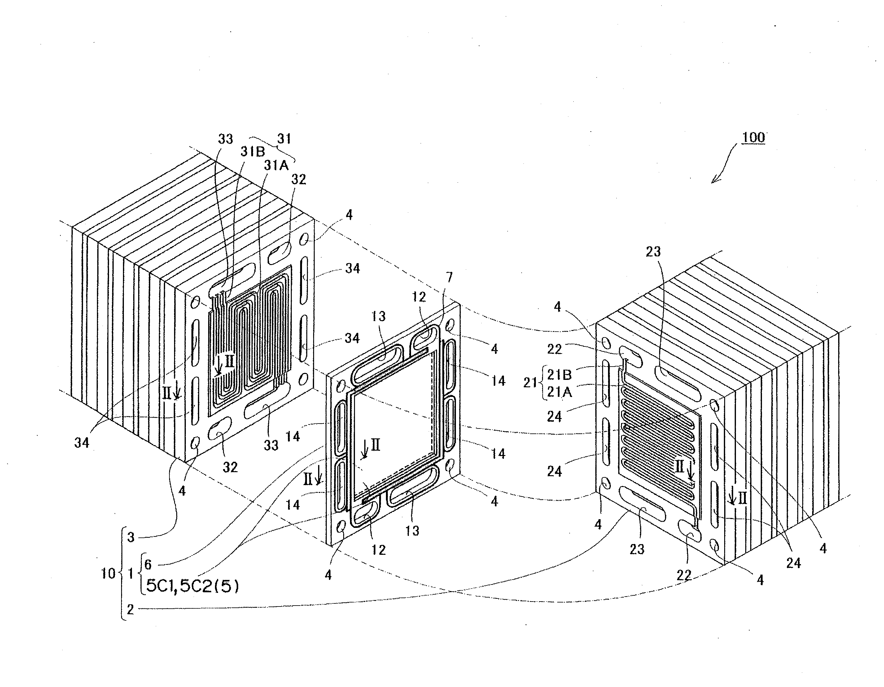
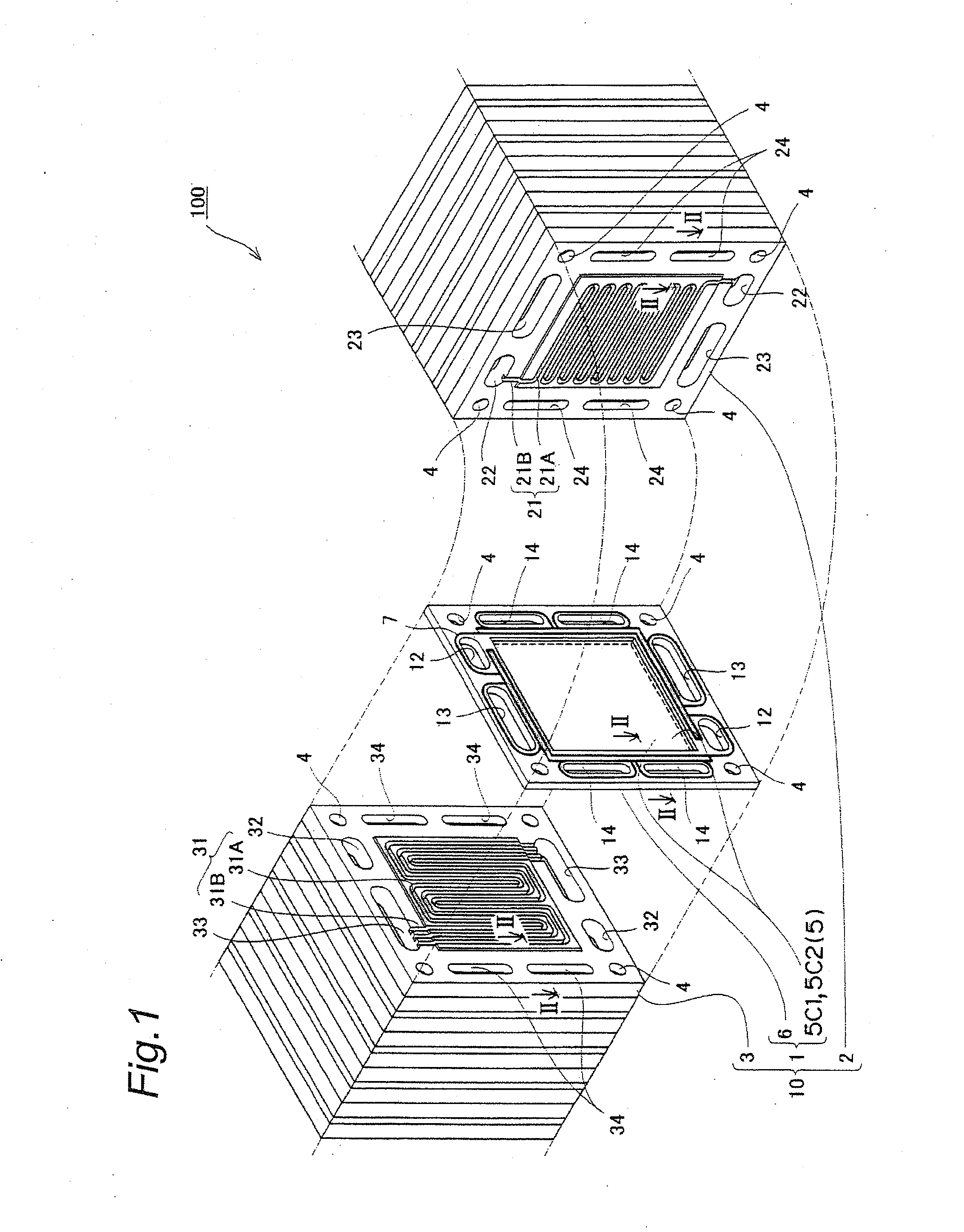
[0099]FIG. 1 is a perspective view wherein a structure of a solid polymer electrolyte fuel cell having an electrode-membrane-frame assembly related to a first embodiment of the invention is partially exploded and schematically illustrated.

[0100]As illustrated in FIG. 1, a solid polymer electrolyte fuel cell (PEFC) 100 is formed so that cells (single-cell modules) 10, which are each a basic unit structure, are laminated onto each other. collector plates, insulating plates, and end plates, which are not illustrated, are fitted to an outmost layers of both ends of the cells 10, and the cells 10 are formed to be pushed from both the ends, and clamped or jointed to each other by means of clamping bolts (not illustrated) inserted into bolt holes 4 and nuts (not illustrated). In the first embodiment, the cells 10 are laminated onto each other in a number of 60, and the bolts inserted into the bolt holes 4 and the nuts are jointed to each other at a jointing force of 10 kN.

[0101]Each of the...

second embodiment

[0156]The following will describe an MEA related to a second embodiment of the invention. FIG. 11A to 11D are schematic explanatory views illustrating steps for producing the MEA related to the second embodiment of the invention, wherein a joint region between an MEA principal part and a frame is enlarged and shown. FIG. 12 is a schematic sectional view of the MEA related to the second embodiment of the invention.

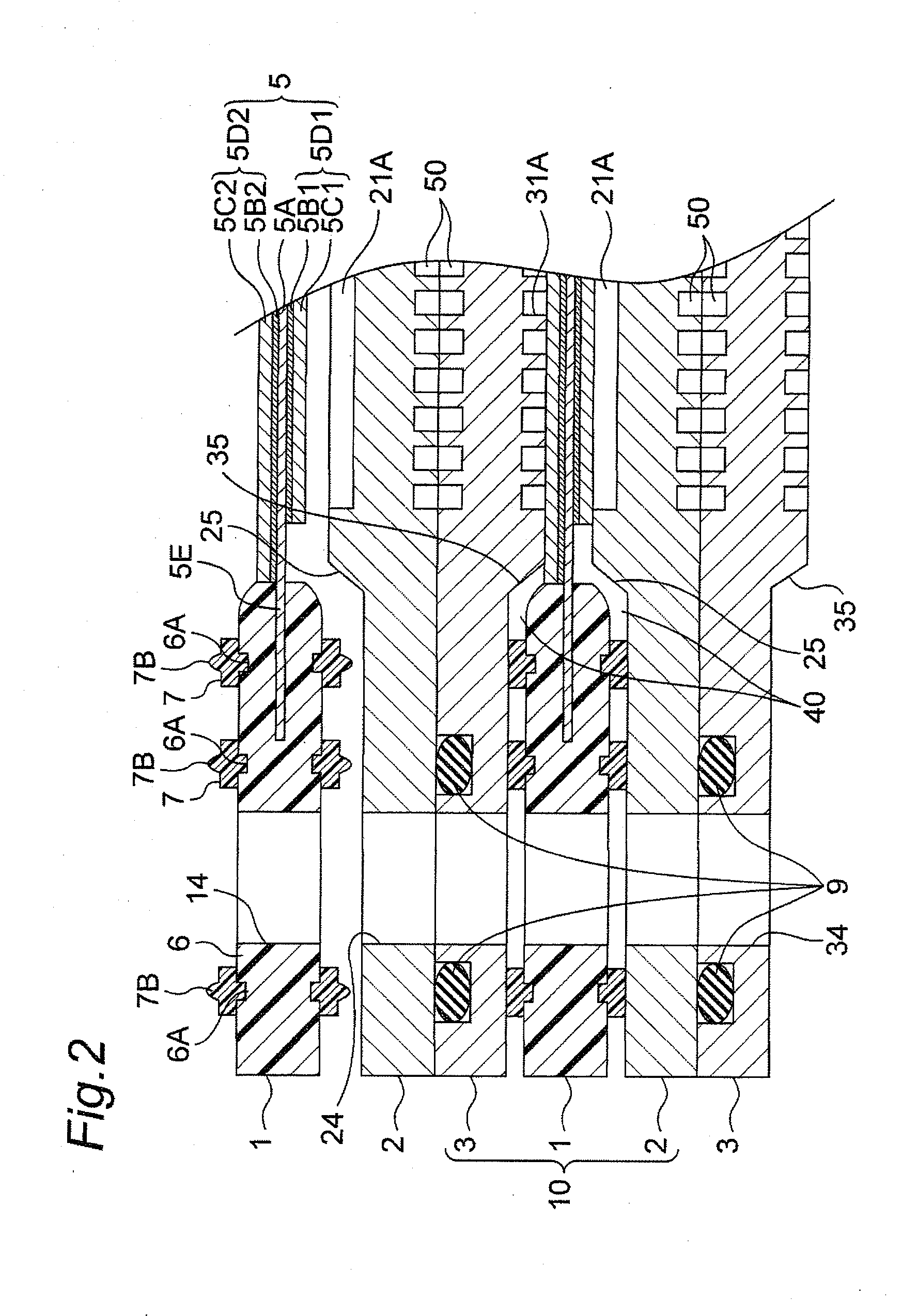
[0157]When the MEA 1 related to the first embodiment is used to constitute any one of the cells 10, gaps 40 are made, as illustrated in FIG. 2, between: a vicinity of the joint region between the frame 6 of the MEA 1 and the MEA principal part 5; and the separators 2 and 3. A fuel gas and an oxidizer gas undergo an electrochemical reaction mainly between the electrode layers 5D1 and 5D2 opposed to each other; however, it is feared that the gaps 40 become a passage for a shortcut so that the fuel gas and the oxidizer gas do not pass between the electrode layers 5D1 and 5D2.

[...

third embodiment

[0166]The following will describe an MEA related to a third embodiment of the invention. The MEA related to the third embodiment of the invention is different only in the structure of its MEA principal part from the MEA related to the first embodiment. The MEA is equal in the others to the MEA related to the first embodiment; thus, overlapping descriptions thereof are omitted.

[0167]FIG. 13 is a plan view of the MEA principal part, which the MEA related to the third embodiment of the invention has. As illustrated in FIG. 13, an MEA principal part 5a has a structure wherein a rectangular anode electrode layer 5D1 and a rectangular cathode electrode layer 5D2 are arranged to cross their long sides (or short sides) with each other (for example, perpendicularly) so that the layers have overhanging portions, where the layers are not opposed to each other. In other words, the cathode electrode layer 5D2 is arranged so that its long sides cross paired long sides of the anode electrode layer...


PUM

PropertyMeasurementUnit
jointing forceaaaaaaaaaa
thicknessaaaaaaaaaa
thicknessaaaaaaaaaa

Abstract

In the method of the invention for producing an electrode-membrane-frame assembly, its principal part is formed by laying a first catalyst layer onto one of surfaces of an electrolyte membrane, arranging a first gas diffusion layer onto the surface of the first catalyst layer and inside the circumferential region of the electrolyte membrane, laying a second catalyst layer onto the other surface of the electrolyte membrane, and arranging a second gas diffusion layer onto the surface of the second catalyst layer and inside the circumferential region of the electrolyte membrane so as to make the position of the outer circumference of the second gas diffusion layer different from that of the outer circumference of the first gas diffusion layer. Then, in the state that an outer circumferential portion of either the first gas diffusion layer or the second gas diffusion layer, the portion being positioned outside a region of the first and second gas diffusion layers wherein the two layers are opposed to each other, is opposed to a portion of a flat region located inside the frame of a frame-form primary molded body, the circumferential region of the principal part is arranged on the flat region, and subsequently a secondary molded body is formed to cover the circumferential region of the electrolyte membrane with the second molded body together with the primary molded body, in order to prevent the polymer electrolyte membrane from being broken or deformed.

Description

TECHNICAL FIELD[0001]The present invention relates to an improvement in a method for producing an electrode-membrane-frame assembly used in a solid polymer electrolyte fuel cell.BACKGROUND ART[0002]Solid polymer electrolyte fuel cells (hereinafter referred to as PEFCs) are devices wherein a fuel gas containing hydrogen and an oxygen-containing oxidizer gas, such as air, are caused to react electrochemically with each other, thereby generating electric power and heat simultaneously.[0003]In general, PEFCs each have a structure wherein plural cells are laminated onto each other. Any one of the cells has a structure wherein a membrane-electrode assembly (hereinafter referred to as an MEA) is sandwiched between a pair of plate-form conductive separators, specifically, an anode separator and a cathode separator. The MEA is equipped with an MEA principal part, and a frame arranged to extend over a circumferential region (or the periphery) of the MEA principal part and further surround the...

Claims


Application Information

Patent Timeline
Patent Type & Authority Applications(United States)
IPC IPC(8): H01M8/00
CPCB29C45/14065B29C45/14836B29C45/1671B29C2045/1673Y02E60/521H01M8/0202H01M8/0286H01M8/1004H01M2008/1095B29L2031/3468Y02P70/50Y02E60/50
Inventor TSUJI, YOICHIROMATSUMOTO, TOSHIHIROKUSAKABE, HIROKIMORIMOTO, TAKASHI
Owner PANASONIC CORP
Why Eureka
Try Eureka