Method for way allocation and way locking in a cache

a cache and memory technology, applied in the field of computing systems, can solve the problems of degrading the average memory latency seen by the core in the system, no useful work to be performed, etc., and achieve the effect of reducing the size of the shared cach

Active Publication Date: 2010-09-30
ADVANCED MICRO DEVICES INC
View PDF19 Cites 106 Cited by
  • Summary
  • Abstract
  • Description
  • Claims
  • Application Information

AI Technical Summary

Benefits of technology

[0011]One or more configuration and status registers (CSRs) are coupled to the shared cache controller for storing encoding values used to enable and disable said allocation separately to each of the shared cache ways. The programming of the stored values in the CSRs may make each of the shared cache ways available for allocation subsequent a cache miss by only one or more preselected sources. Therefore, a particular first source, such as an I/O device, may not have allocati

Problems solved by technology

However, a stall in a pipeline may cause no useful work to be performed during that particular pipeline stage.
Since this allocation strategy does not distinguish requests from different sources, it may allow one source, such as an I

Method used


Image

  • Method for way allocation and way locking in a cache
  • Method for way allocation and way locking in a cache
  • Method for way allocation and way locking in a cache

Examples


Embodiment Construction

[0021]In the following description, numerous specific details are set forth to provide a thorough understanding of the present invention. However, one having ordinary skill in the art should recognize that the invention may be practiced without these specific details. In some instances, well-known circuits, structures, and techniques have not been shown in detail to avoid obscuring the present invention.

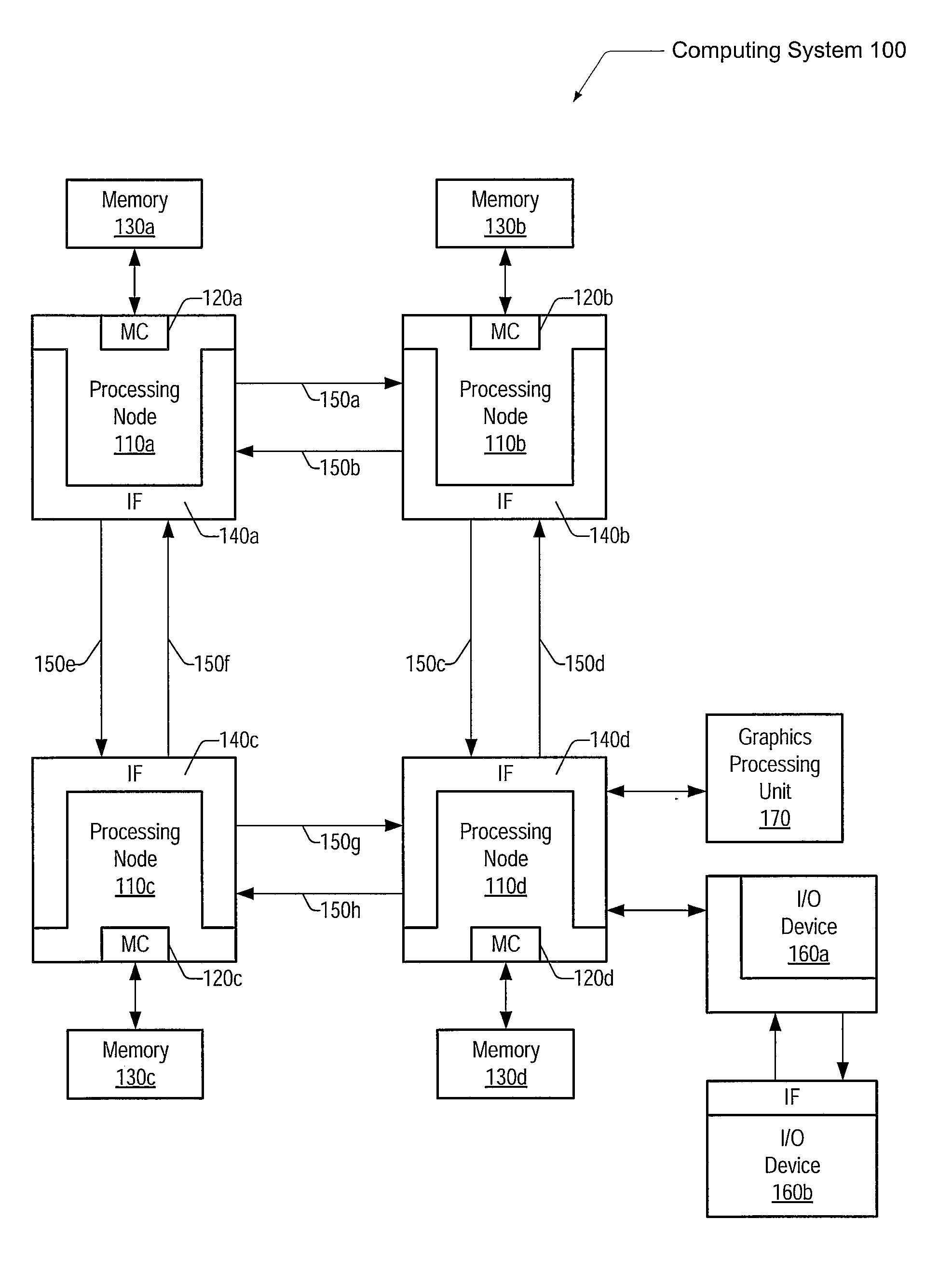
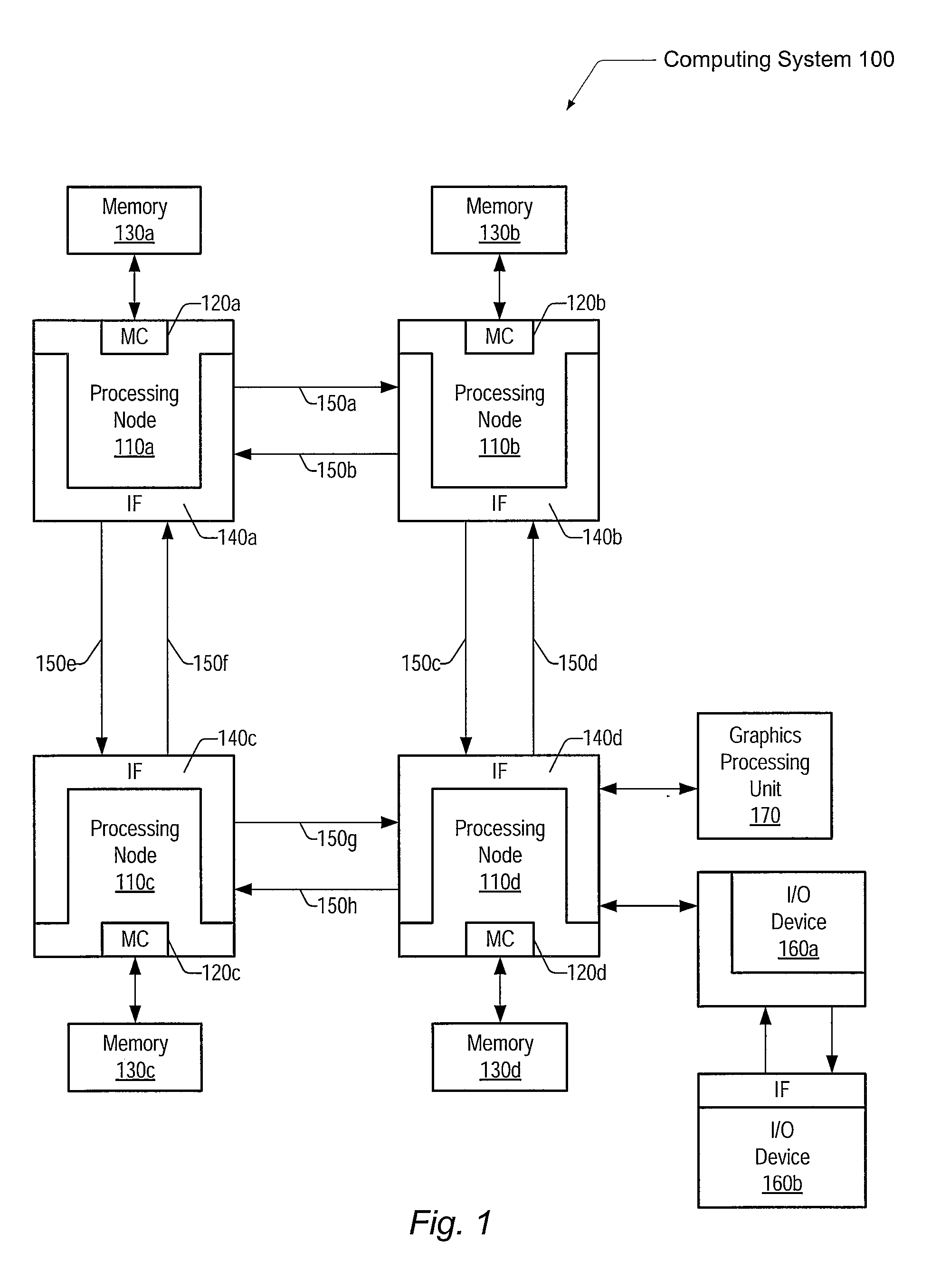
[0022]Referring to FIG. 1, one embodiment of a computing system 100 is shown. Generally speaking, computing system 100 includes a plurality of processing nodes 110a-110d. As used herein, elements referred to by a reference numeral followed by a letter may be collectively referred to by the numeral alone. For example, processing nodes 110a-110d may be collectively referred to as processing nodes 110, or nodes 110. Although four nodes 110 are shown in FIG. 1, other embodiments may comprise one, two, six, or any different number of nodes, wherein each node 110 comprises one or more proc...


PUM


Abstract

A system and method for data allocation in a shared cache memory of a computing system are contemplated. Each cache way of a shared set-associative cache is accessible to multiple sources, such as one or more processor cores, a graphics processing unit (GPU), an input/output (I/O) device, or multiple different software threads. A shared cache controller enables or disables access separately to each of the cache ways based upon the corresponding source of a received memory request. One or more configuration and status registers (CSRs) store encoded values used to alter accessibility to each of the shared cache ways. The control of the accessibility of the shared cache ways via altering stored values in the CSRs may be used to create a pseudo-RAM structure within the shared cache and to progressively reduce the size of the shared cache during a power-down sequence while the shared cache continues operation.

Description

BACKGROUND OF THE INVENTION[0001]1. Field of the Invention[0002]This invention relates to computing systems, and more particularly, to data allocation in a shared cache memory of a computing system.[0003]2. Description of the Relevant Art[0004]Modern microprocessors may include one or more processor cores, or processors, wherein each processor is capable of executing instructions of a software application. These processors are typically pipelined, wherein the processors include one or more data processing stages connected in series with storage elements (e.g. registers and arrays) placed between the stages. Although the pipeline may be divided into any number of stages at which portions of instruction processing are performed, instruction processing generally comprises fetching the instruction, decoding the instruction, executing the instruction, and storing the execution results in the destination identified by the instruction.[0005]Ideally, every clock cycle produces useful execut...

Claims


Application Information

Patent Timeline
IPC IPC(8): G06F12/08G06F12/00
CPCG06F12/0804G06F12/084Y02B60/1225G06F12/126G06F12/0888Y02D10/00G06F12/08
Inventor OWEN, JONATHANKRISHNAN, GUHANDIETZ, CARL D.BEARD, DOUGLAS RICHARDLEWCHUK, WILLIAM K.BRANOVER, ALEXANDER
Owner ADVANCED MICRO DEVICES INC
Why Eureka
Try Eureka