Injector for Arc Furnace

Active Publication Date: 2010-10-07
CONCAST AG
View PDF6 Cites 8 Cited by
  • Summary
  • Abstract
  • Description
  • Claims
  • Application Information

AI Technical Summary

Benefits of technology

[0011]Particularly, the task of the present invention is to provide

Problems solved by technology

These are very hard operating conditions, which cause the injector to be very rapidly worn.
Considerable wear levels of the injector can cause a water leakage from the cooling circuit within the furnace, with a consequent worsening in the operating conditions.
Furthermore, any water infiltration below the layer of refractory material may cause the formation of vapour that results in a rapid volume and pressure increase having the effect of an actual explosion.
A water leakage at the furnace operating temper

Method used


Image

  • Injector for Arc Furnace
  • Injector for Arc Furnace
  • Injector for Arc Furnace

Examples


Example

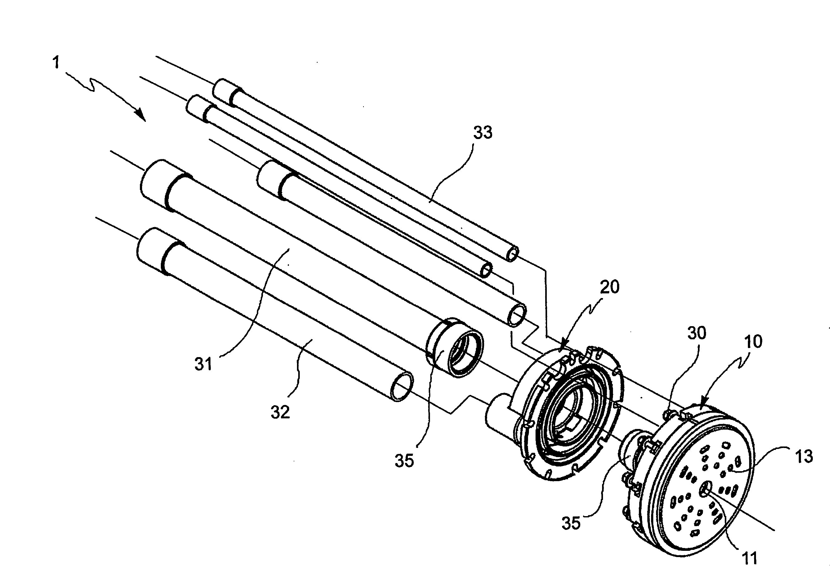
[0029]With reference to the annexed figures, with 1 has been generally designated an injector according to the invention.

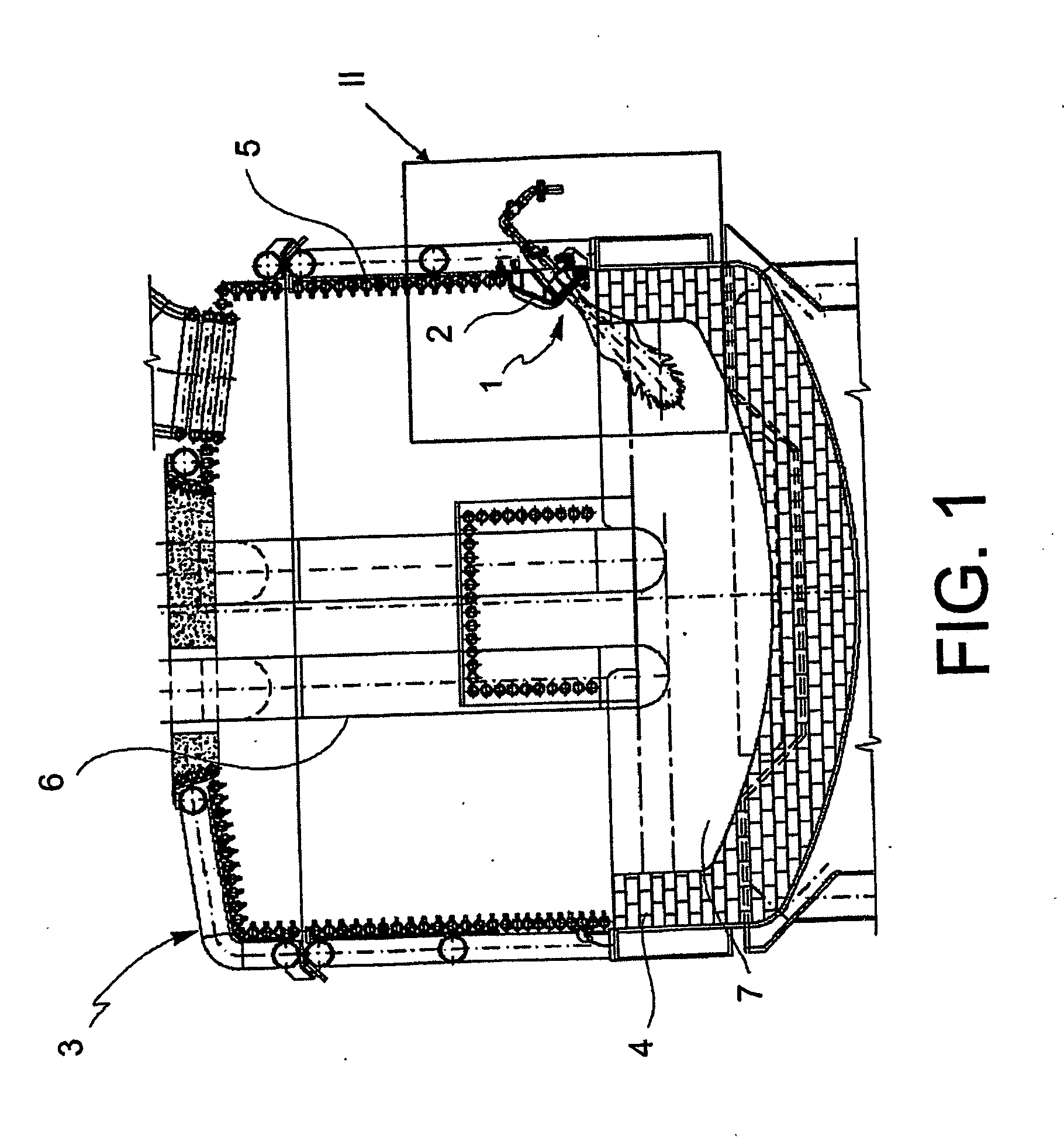
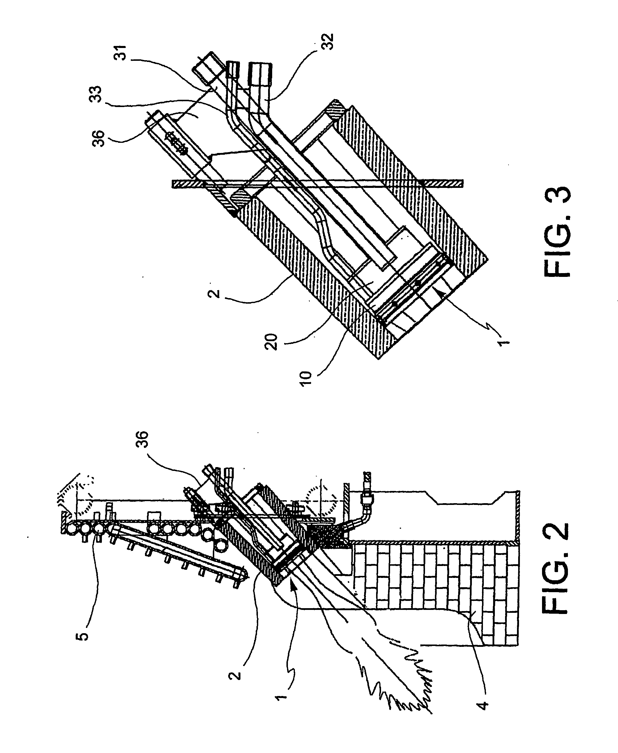
[0030]With particular reference to FIGS. 1 and 2, the injector 1, protected by a cooled case2, is placed in an opening operated in the side wall of an arc furnace 3. In a manner known per se, the arc furnace 3 comprises an inner lining 4 made of refractory material, a cooling system 5, electrodes 6 and, upon operation, a molten metal bath 7.

[0031]The injector 1 according to the invention, comprises a head 10 and a body 20. The head is suitable to face into the arc furnace 3. The body 20 is suitable to support the head 10. The head 10 and body 20 are made separately from each other and are fastened by means of removable connection means 30 in order to implement the injector 1.

[0032]The embodiments of the injector 1 discussed below have a substantially axially symmetrical shape. For clarity purposes, the description herein below will refer to this shape, though it i...


PUM

PropertyMeasurementUnit
Flow rateaaaaaaaaaa
Speedaaaaaaaaaa
Shapeaaaaaaaaaa

Abstract

The present invention relates to an injector for an arc furnace. The injector comprises a head suitable to face into the furnace and a body suitable to support the head. The head and body are manufactured separately from each other, and are fastened by means of removable connection means in order to implement said injector.

Description

FIELD OF THE INVENTION[0001]The object of the present invention is an injector for electric arc furnaces for steel melting.BACKGROUND OF THE INVENTION[0002]In the field of electric arc furnaces for use in the iron and steel industry, it is known to make openings on the side walls of the furnace chamber (or shaft). Devices (or injectors) such as auxiliary burners and / or lances can be inserted through these openings.[0003]Particularly, it is known to use auxiliary burners that allow adding further amounts of heat to the heat provided by the electric arc in order to facilitate and accelerate metal bulk melting. It is also known to use dispensers that are capable of simultaneously injecting gases and powders into the shaft. By “lance” is normally meant a supersonic gas dispenser or a high-speed powder dispenser. Dispensers and lances, besides functioning as gas injectors or burners, allow introducing additives in the molten metal bath, which are used during the metallurgical process, su...

Claims


Application Information

Patent Timeline
IPC IPC(8): F27B3/22C21C5/52F27D99/00
CPCC21C5/5217F23D14/22F23D14/48F23D14/78F23D17/005F27D99/0033F23D2900/00006F27B3/20F27B3/205F27B3/22F27B3/225F23D2212/20Y02P10/20
Inventor MIANI, STEFANORUBEO, BRUNO
Owner CONCAST AG
Why Eureka
Try Eureka