LED bulb

Inactive Publication Date: 2010-10-07
LIQUIDLEDS LIGHTING
View PDF9 Cites 60 Cited by
  • Summary
  • Abstract
  • Description
  • Claims
  • Application Information

AI Technical Summary

Benefits of technology

[0011]Preferably, the side-emitting LEDs are mounted on the peripheral region of the mounting surface of the substrate that they are mounted thereon, to provide lateral light and thereby increase the lighting a

Problems solved by technology

The conventional incandescent bulb, though capable of a wide lighting angle, is disadvantageous because of its high power consumption, high temperature, and short lifetime.
However, the limited lighting angle and high production costs of LED bulbs have restricted their applicability in our daily lives.
However, this LED bulb still has its drawbacks such as high production costs, difficult assembly, and a hard-to-control yield.
In addition, a wide lighting angle is unattainable if fewer LEDs are used.
Consequently, the LED bulb cannot provide effective lateral illumination.
On the other hand, while it is common practice to connect several through-hole LEDs together for multi-angle light emission, the slender pins typical

Method used


Image

  • LED bulb
  • LED bulb
  • LED bulb

Examples


Embodiment Construction

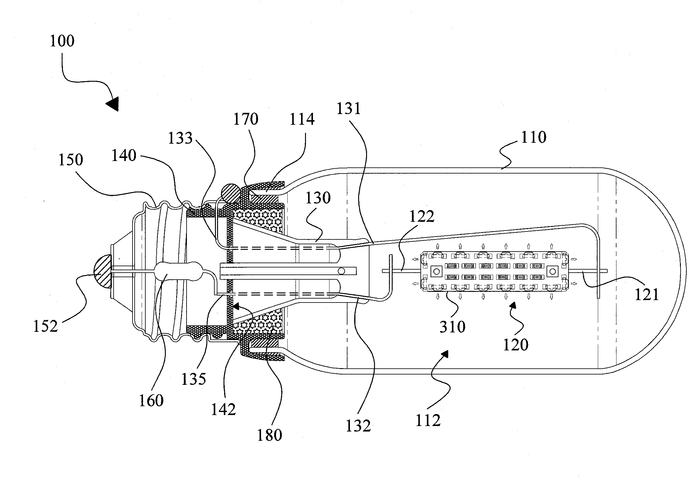
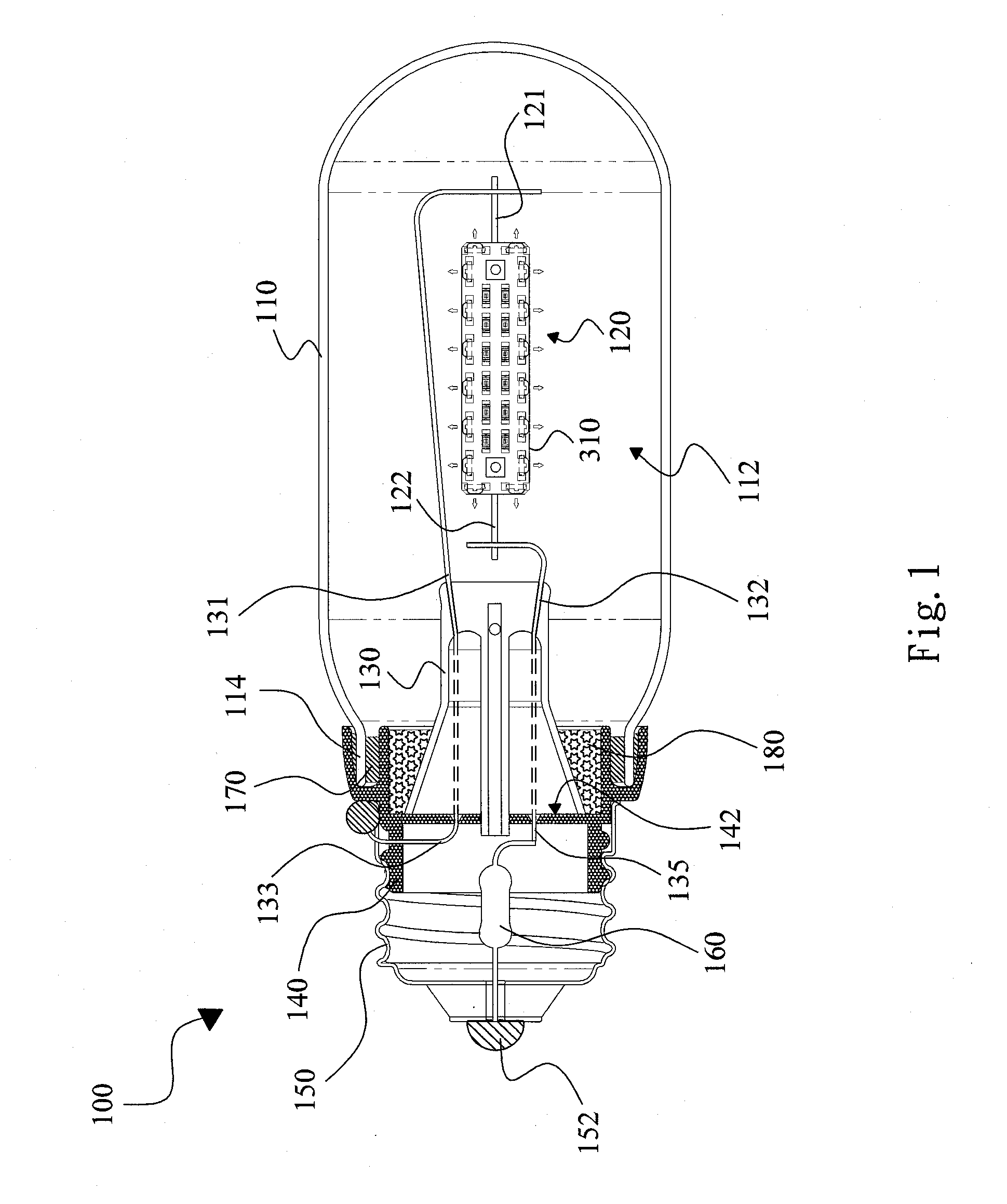
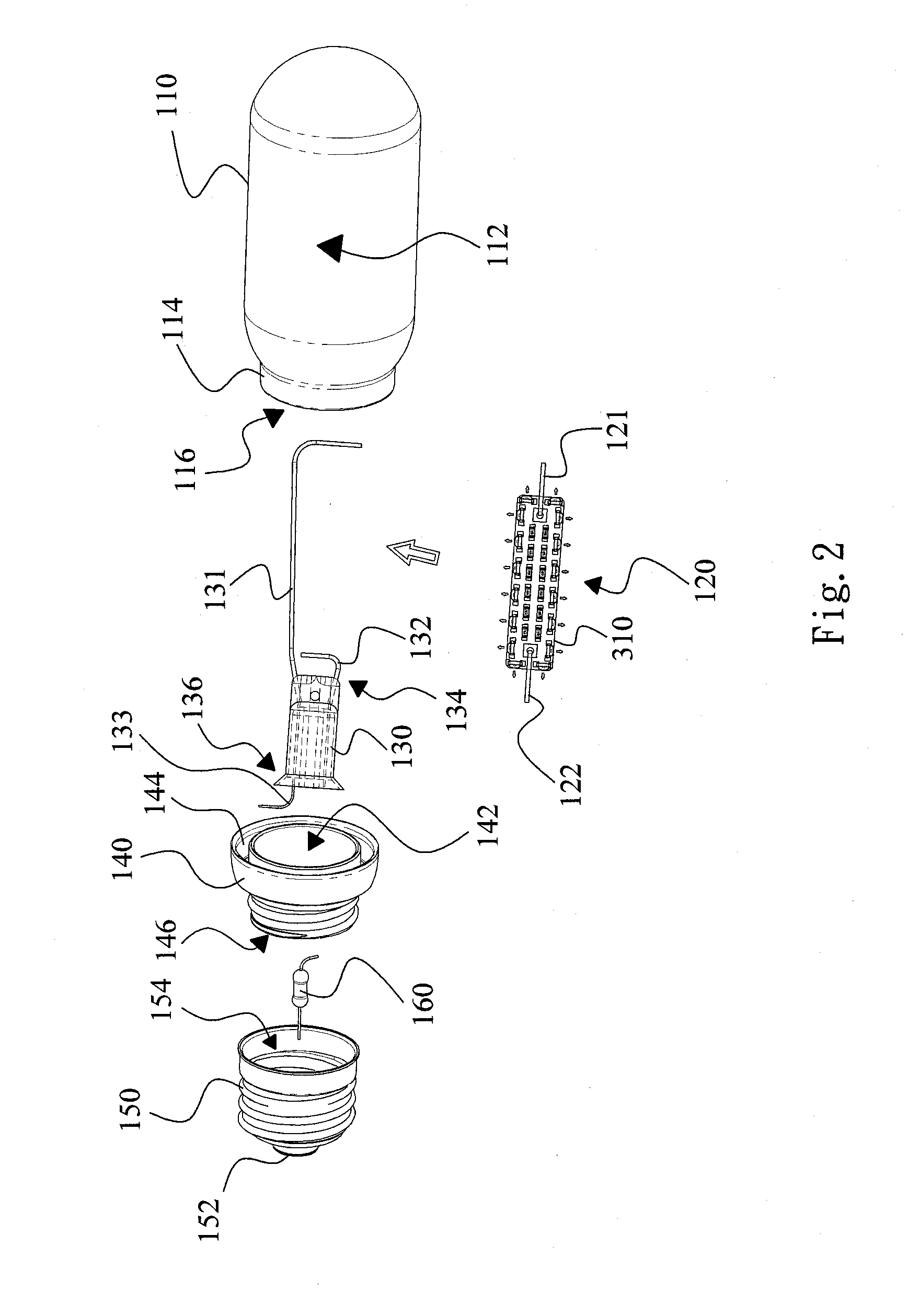
[0021]FIG. 1 shows an LED bulb 100 according to an embodiment of the present invention; FIGS. 2 and 3 show the exploded view and circuit diagram of the LED bulb 100 of the present invention. The LED bulb 100 includes a housing 110 and a bulb base 150 joined to or combined together by a member 140. In this embodiment, the housing 110 has an end 114 inserting into a groove 144 of the member 140, with a securing medium 170, for example a glue, filled in the groove 144 to secure the housing 110 at the front side of the member 140, and the bulb base 150 is secured at the rear side of the member 140, for example, by means of snug fit or adhesive. As is well known, the bulb base 150 has two electrodes to be connected to an external power source 230, and the housing 110 has a cavity 112 for containing a filament. A stem 130 has lead frames 131 and 132 extending from the front end 134 of the stem 130 into the cavity 112 of the housing 110, and an LED strip 120 is suspended between the lead f...


PUM


Abstract

An LED bulb uses an LED strip suspended between two lead frames of a stem as a light source to provide uniform illumination with wider angles. The lead frames of the stem provide an improved structural stability to the LED strip while maintaining a reliable electrical connection between the components of the stem and the LED strip. The utilization of both top-emitting and side-emitting LEDs on the LED strip further allows lights emitted in directions substantially parallel and perpendicular to the LED strip to cover a wide angle of illumination from the LED bulb.

Description

FIELD OF THE INVENTION[0001]The present invention is related to a light bulb and, more particularly, to a light-emitting diode (LED) bulb that may be used as a replacement light bulb.BACKGROUND OF THE INVENTION[0002]Conventional incandescent bulbs mostly include a conductive filament, such as a tungsten filament, supported by lead frames which are connected to an external power source via a bulb base to supply electricity to the filament. The filament is rendered incandescent by current flowing therethrough and thus generates light that radiates outward uniformly and extensively. The conventional incandescent bulb, though capable of a wide lighting angle, is disadvantageous because of its high power consumption, high temperature, and short lifetime. By contrast, a light-emitting diode (LED) bulb has a long lifetime, is power saving, produces no wastes that may cause pollution, and is therefore environmentally friendly. Hence, LED bulbs are gradually replacing the conventional incand...

Claims


Application Information

Patent Timeline
IPC IPC(8): H01K1/62H01J5/48
CPCF21K9/00F21Y2101/02F21K9/135F21Y2111/001F21V17/101Y10S362/80F21V3/02F21K9/232F21Y2115/10F21Y2107/00F21Y2107/90
Inventor CHIANG, KUN-YUAN
Owner LIQUIDLEDS LIGHTING
Why Eureka
Try Eureka