
Self-Aligning Construction for Flashlight Products

a technology of self-aligning construction and flashlight products, which is applied in the direction of electric lighting with batteries, semiconductor devices of light sources, lighting and heating apparatus, etc., can solve the problems of substantial consumption of power and not well-adapted to certain industrial or mobile uses, and achieve the effect of improving the structure and function of lighting instruments

Inactive Publication Date: 2010-10-07
BAYCO PRODS
View PDF6 Cites 25 Cited by
  • Summary
  • Abstract
  • Description
  • Claims
  • Application Information

AI Technical Summary

Benefits of technology

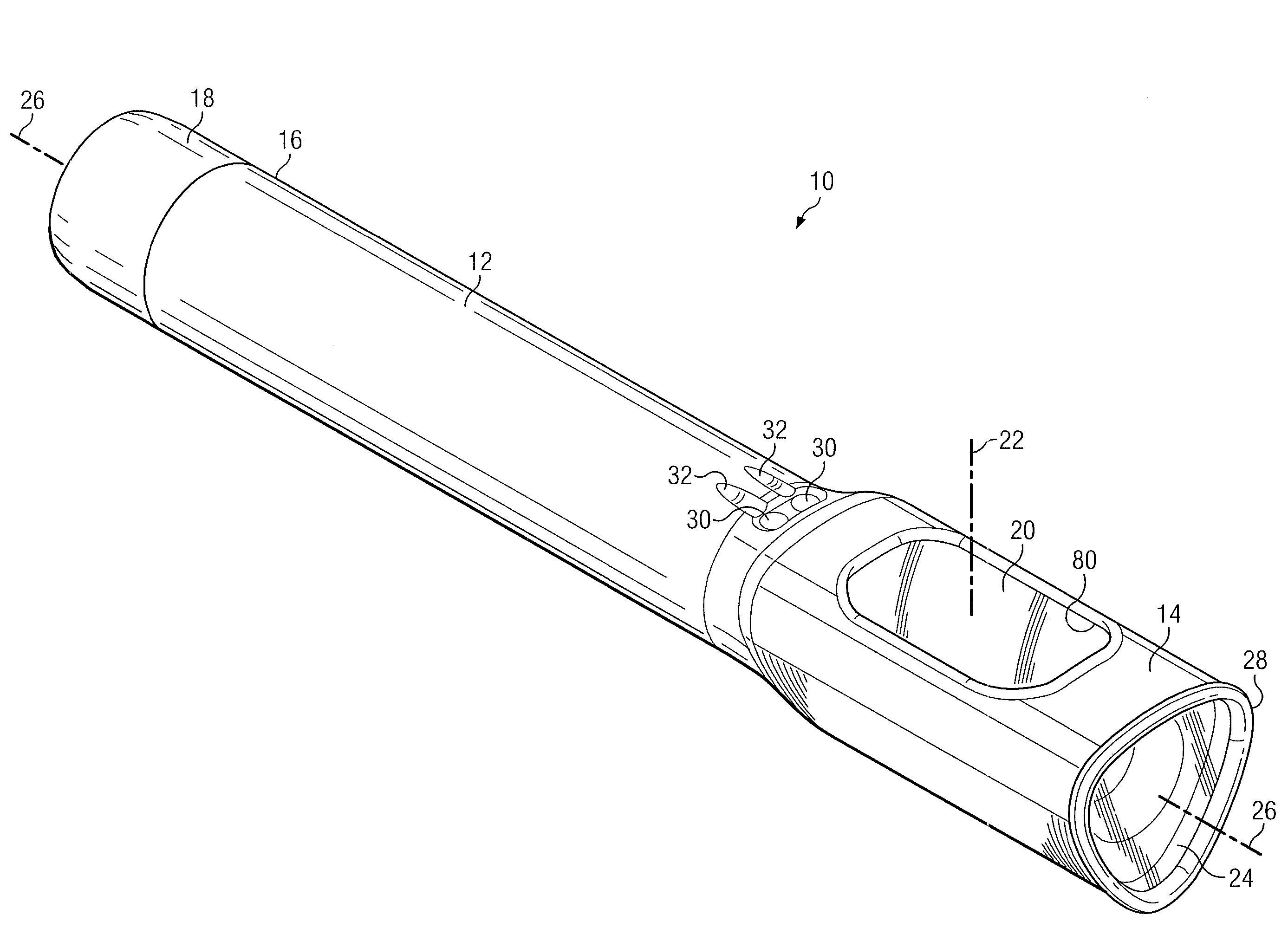
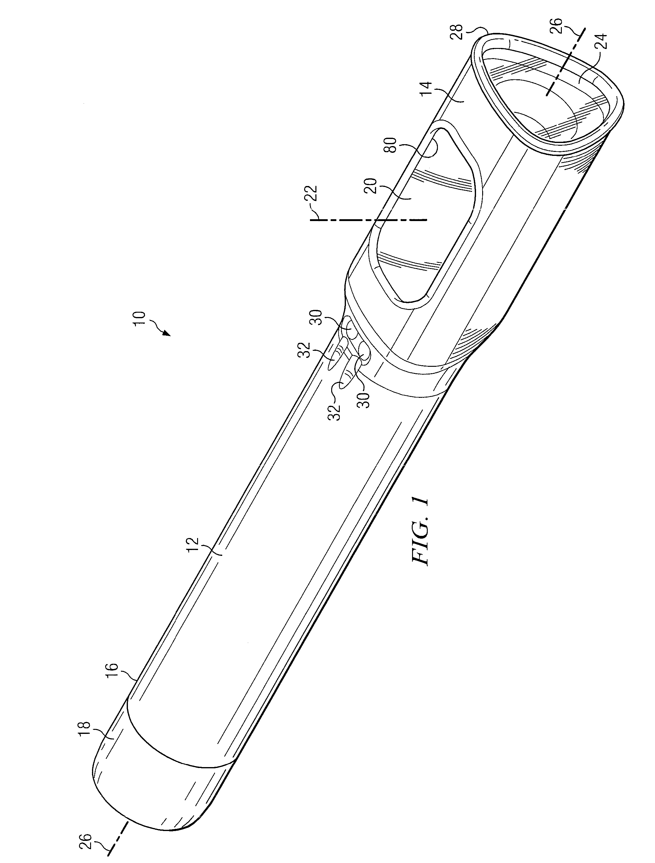
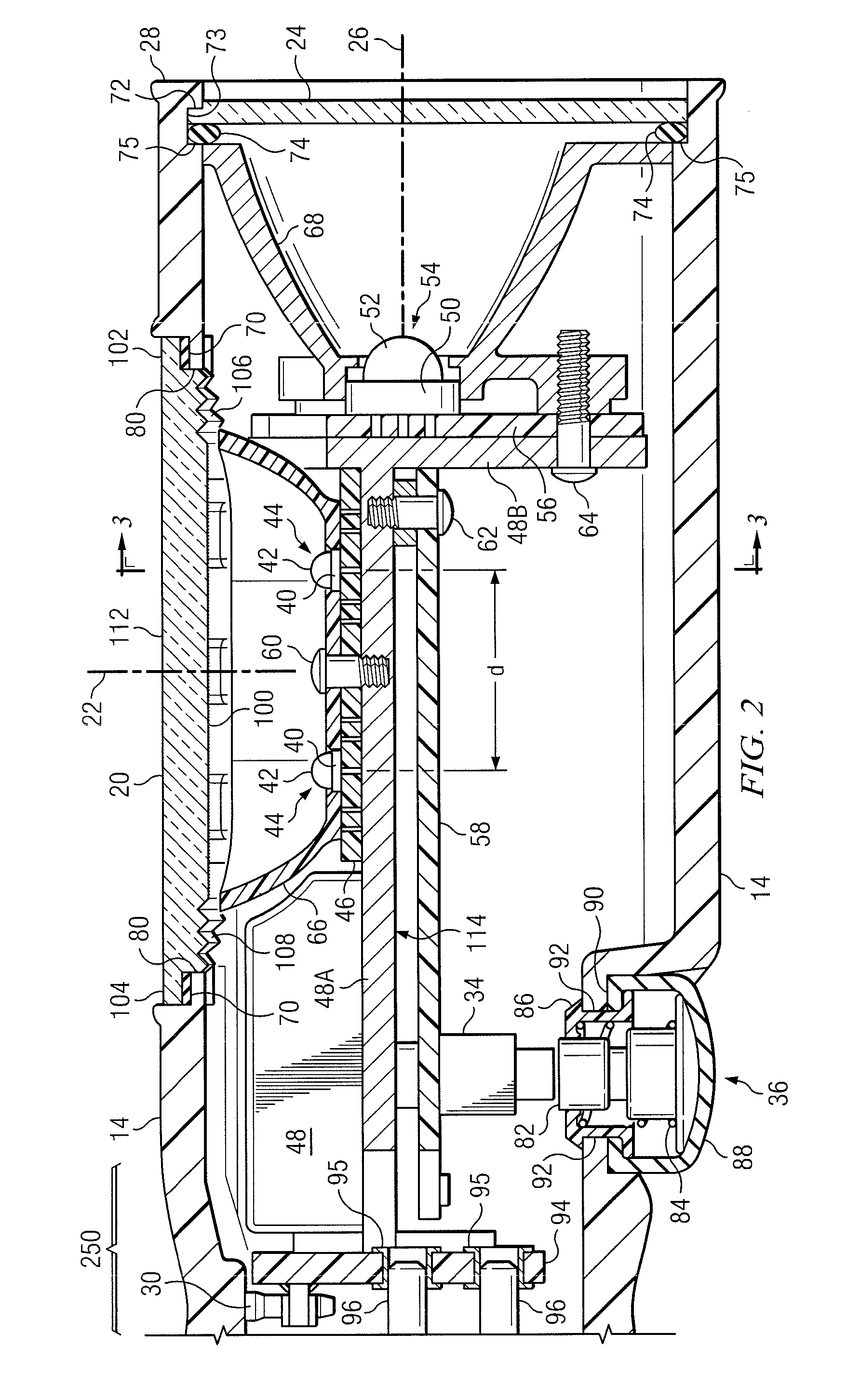
[0006]Accordingly, further developments have improved the structure and function of lighting instruments and adapted them to additional uses as will be disclosed herein. Among the improvements are smaller, more compact construction, optical structures that provide brighter and more uniform illumination, push button actuators and lenses that are sealed against moisture and dust, housing structures that automatically align critical components during assembly, a self-aligning docking station for recharging internal batteries without removing them from the instrument, and the like.
[0007]In another embodiment a sealed push button actuator assembly for installation in an opening in the wall of a housing of an appliance is provided comprising an actuator assembly including a grommet having disposed there within a push button plunger having a concentric spring there around and configured for sliding movement against tension in the spring within the grommet; and a resilient boot enclosing portions of the actuator assembly external to the housing, the boot having a circumferential, inward-extending lip clamped between the grommet and the periphery of the opening in the housing, to provide a dust and moisture resistant seal of the opening.

Problems solved by technology

As useful as these lighting devices have become, they are relatively large, consume substantial power, and are not well-adapted to certain industrial or mobile uses.

Method used


Image

  • Self-Aligning Construction for Flashlight Products
  • Self-Aligning Construction for Flashlight Products
  • Self-Aligning Construction for Flashlight Products

Examples


Embodiment Construction

[0030]The inventions disclosed herein embody solutions to several problems with existing lighting instruments such as, for example, hand held flashlights. These solutions provide such useful advantages as reduced power consumption; smaller size and lower weight; more uniform beams of light; better use of flood and spot light beams; the capability of being used in hazardous environments; and the like. Accordingly, a number of new features and improvements to lighting instruments have been developed that advance the state of the art.

[0031]In lighting instruments designed for use in hazardous environments it is important to provide a housing or case that is sealed against dust and moisture, among other properties. Thus, any structure or component that must pass through the wall of the housing or case must be fully sealed. In conventional apparatus it is known to provide some mechanism to seal the component with respect to the housing. However, this can be a problem when the operative a...


PUM


Abstract

An electronic lighting instrument features separate optical assemblies for flood lighting and spot lighting. The optical assemblies include primary, secondary, and tertiary optical elements. The housing of the instrument features a trilobal cross section and includes dust-and-moisture-sealed push buttons and lenses as part of the housing construction. Self-aligning assemblies to ensure correct electrical and mechanical assembly are provided. The housing also self-aligns with a mating docking station for recharging the instrument batteries in situ. The lighting instrument may be controlled by a microprocessor circuit to provide floodlight and spotlight beams and several operational states thereof depending on the need for illumination or signaling.

Description

CROSS REFERENCE TO RELATED APPLICATIONS[0001]The present application claims priority from an earlier filed provisional patent application Ser. No. 61 / 166,500, entitled “Flashlight With Multiple Modes,” filed Apr. 3, 2009, by the same inventors. This application is also related to U.S. patent application entitled “Sealed Switch Actuator for Appliances” and U.S. patent application entitled “Optical Apparatus for Hand Held Lamps,” by the same inventors.BACKGROUND OF THE INVENTION[0002]1. Field of the Invention[0003]The present invention generally relates to handheld lighting instruments and more particularly to optical apparatus for electronic lighting instruments having multiple modes of operation, including flood light and spotlight beams in an ergonomic structure for meeting industrial requirements.[0004]2. Description of the Prior Art[0005]Hand held lighting instruments have benefited greatly from the development and availability of light emitting diodes, other compact light source...

Claims


Application Information

Patent Timeline
IPC IPC(8): F21L4/00F21L4/04
CPCF21L4/027F21V15/01F21V23/0414F21L4/08F21Y2101/02F21Y2115/10
Inventor BAYAT, BIJANKEMPTER, MARK W.NEWTON, JAMES L.
Owner BAYCO PRODS
Learn More