Video coding method, video decoding method, video coding apparatus, video decoding apparatus, and corresponding program and integrated circuit
a video coding and video decoding technology, applied in the field of video coding filters, can solve the problems of subjective annoying, often having blocking characteristics of superimposed noise, etc., and achieve the effect of reducing prediction errors and reconstruction errors and increasing coding efficiency
- Summary
- Abstract
- Description
- Claims
- Application Information
AI Technical Summary
Benefits of technology
Problems solved by technology
Method used
Image
Examples
embodiment 1
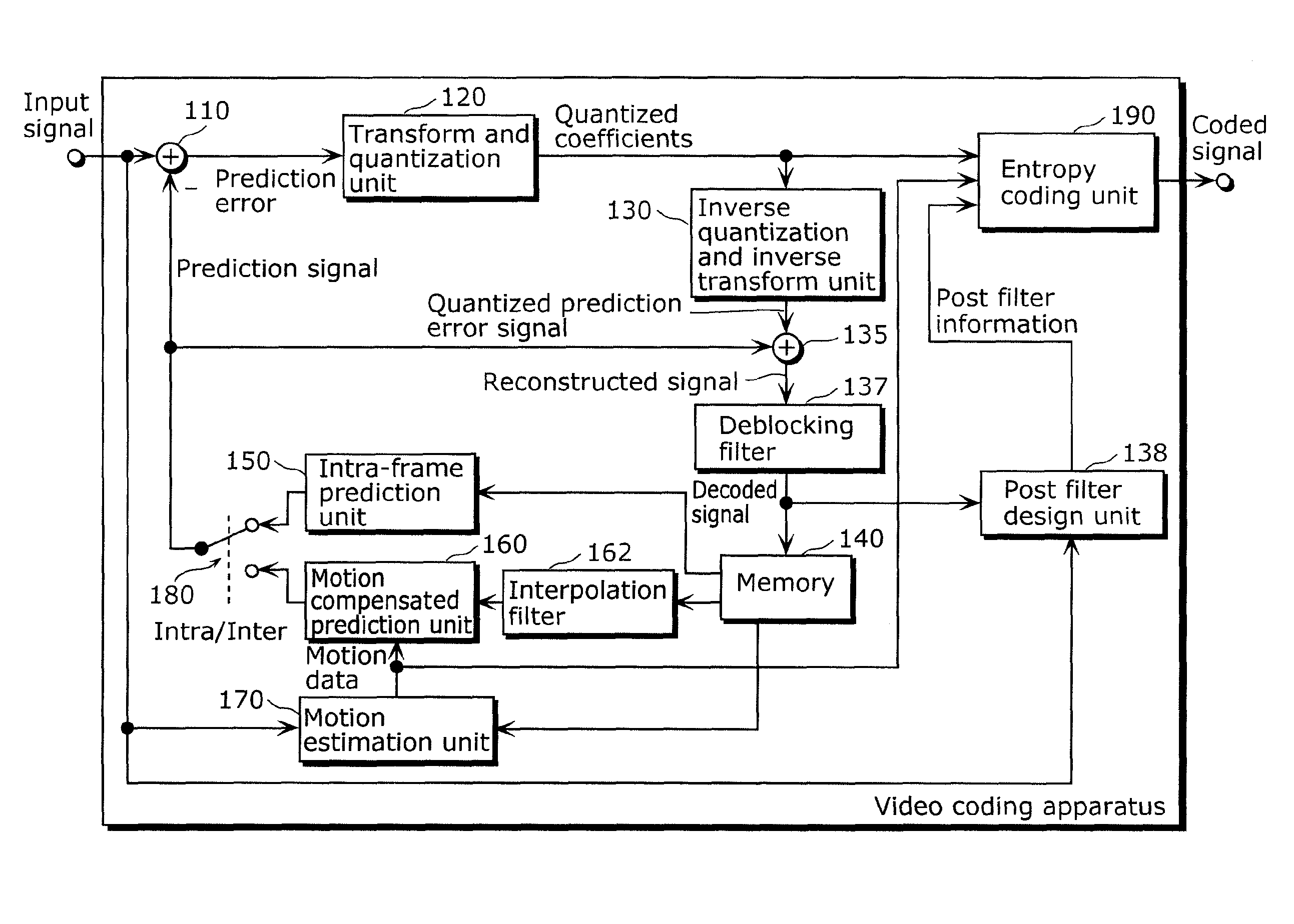
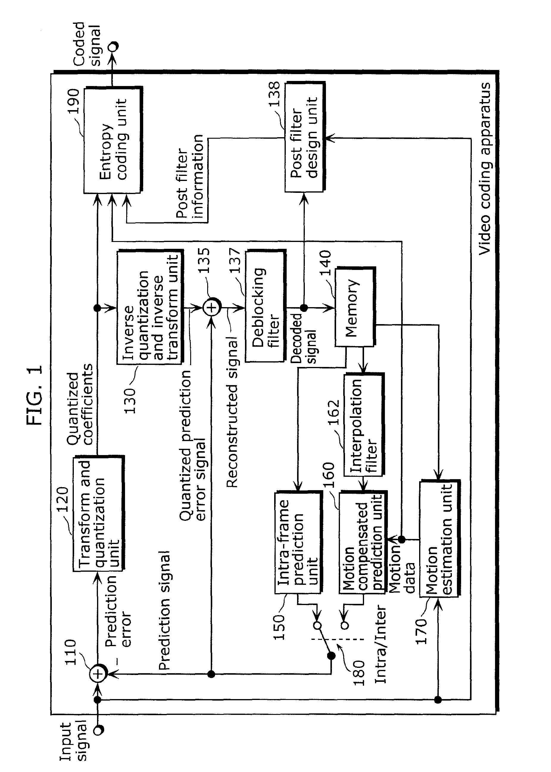
[0086]FIG. 3A is a block diagram of a video coding apparatus 100 according to Embodiment 1 of the present invention. FIG. 3B is a flow chart indicating operations of the video coding apparatus 100 in FIG. 3A. The block diagram of FIG. 3A is similar to that of the conventional video coding apparatus shown in FIG. 1, wherein like components are denoted by like reference numerals. A repetition of the detailed description of these components will be omitted.
[0087]The video coding apparatus 100 shown in FIG. 3A includes a subtractor 110, a transform and quantization unit 120, an inverse quantization and inverse transform unit 130, a post filter design unit (filter information generation unit) 138′, an entropy coding unit 190, and a prediction signal generation unit 200. This video coding apparatus 100 codes a signal to be coded which represents a video, and outputs the coded signal.
[0088]The subtractor 110 generates a prediction error signal by subtracting the prediction signal from the ...
embodiment 2
[0114]FIG. 5 is a block diagram of a video coding apparatus 100 according to Embodiment 2 of the present invention. The block diagram of FIG. 5 is similar to that of the conventional video coding apparatus shown in FIG. 3A, wherein like components are denoted by like reference numerals. A repetition of the detailed description of these components will be omitted.
[0115]The video coding apparatus 100 according to Embodiment 2 of the present invention differs from the conventional video coding apparatus in having the post filter 139 and the additional second post filter design unit 138′. In addition, the video coding apparatus 100 further differs from the video coding apparatus 100 shown in FIG. 3A in having the first post filter design unit 138 and the post filter 139. Further, the second post filter design unit 138′ generates the third filter information based on the statistical properties of the output signal of the post filter 139, in addition to exerting the function of the post f...
embodiment 3
[0123]FIG. 7 is a block diagram of a video coding apparatus 100 according to Embodiment 3 of the present invention. The block diagram of FIG. 7 is similar to that of the video coding apparatus 100 shown in FIG. 3A, wherein like components are denoted by like reference numerals. A repetition of the detailed description of these components will be omitted.
[0124]The video coding apparatus 100 according to Embodiment 3 of the present invention differs from the conventional video coding apparatus and the video coding apparatus 100 shown in FIG. 3A in that the adder 135 and the deblocking filter 137 are replaced by a new loop filter 137′ and a corresponding new loop filter design unit 138′. However, although the post filter design unit 138′ shown in FIG. 3A and the post filter design unit 138″ are different from each other in terms of whether the resulting filter information is used by the post filter 139″ or the loop filter 137′, the filter information generation process itself is the sa...
PUM
 Abstract
Description
Claims
Application Information
 - R&D
- Intellectual Property
- Life Sciences
- Materials
- Tech Scout
- Unparalleled Data Quality
- Higher Quality Content
- 60% Fewer Hallucinations
Browse by: Latest US Patents, China's latest patents, Technical Efficacy Thesaurus, Application Domain, Technology Topic, Popular Technical Reports.
© 2025 PatSnap. All rights reserved.Legal|Privacy policy|Modern Slavery Act Transparency Statement|Sitemap|About US| Contact US: help@patsnap.com


