Fabric and Fabric Laminate

a fabric and laminate technology, applied in the field of fabric improvement, can solve the problems of loss of the textile nature of the fabric, loss of the water repellentness of the fabric, and wet fabrics, and achieve the effects of no sticky touch, firm grip, and good feel

Inactive Publication Date: 2010-10-07
STUEBIGER WERNER
View PDF11 Cites 49 Cited by
  • Summary
  • Abstract
  • Description
  • Claims
  • Application Information

AI Technical Summary

Benefits of technology

[0015]The filling of the voids between the fibers with the polymer material prevents the absorption of water into said voids. The polymer material is substantially only located within the voids of the yarn and has embedded the fibers within the outer surface of said yarn. Therefore, the outer surface of said yarn remains substantially unchanged and at least partially free of polymer material. At least partially free of polymer material means that small portions of the polymer material may stay on parts of the outer surface of the yarn as a very thin layer after the impregnation process. This leads to a fabric with a substantia

Problems solved by technology

This wicking process results in a textile that will be wet, heavy and is very often difficult to dry.
But these fabrics lose their water repellency after just a few washes.
On the other hand the complete coating of the yarns leads to the loss of the textile nature of the fabric.
The soft and textile hand of the fabric no longer exists

Method used


Image

  • Fabric and Fabric Laminate
  • Fabric and Fabric Laminate
  • Fabric and Fabric Laminate

Examples


example 1

[0117]A fabric made of 100% polyester (PES) yarn is used, The fabric is a woven textile made of a filament yarn with a twist level of about 600 turns / m and dtex 100 f36×2. The yarn is non-texturized. The interstices between the yarns have a diameter of about 180 μm-230 μm in the warp and weft direction. Such a woven textile is available from the company SR-Webatex GmbH, Germany.

[0118]FIGS. 7 and 8 show an SEM of the cross section of the yarn of example 1 before the impregnation in different magnifications.

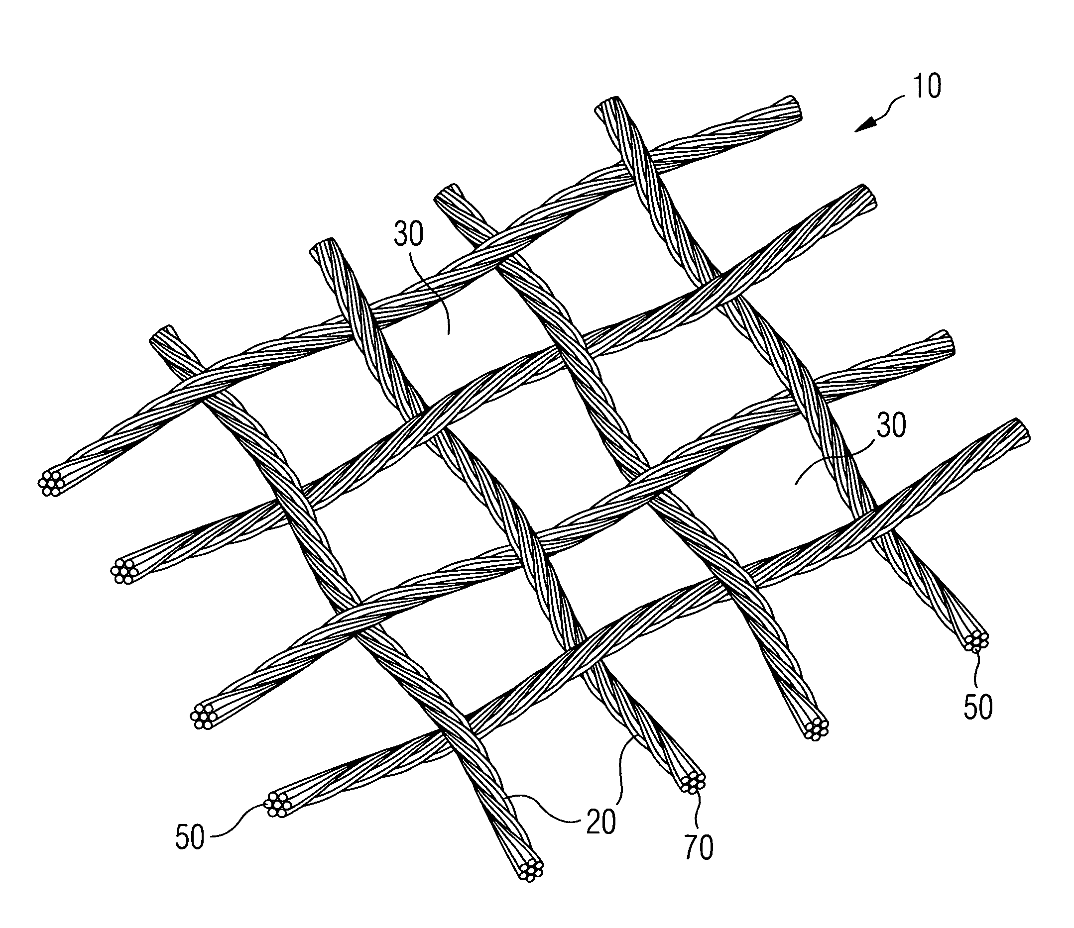
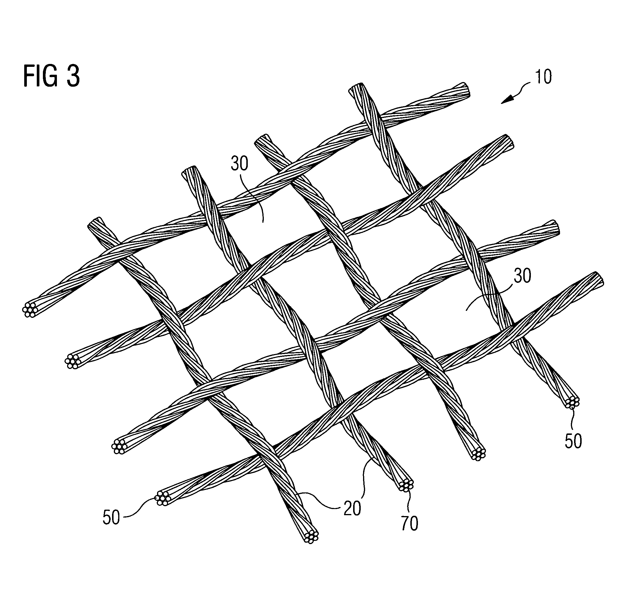
[0119]FIG. 7 shows an SEM of several untreated yarns 20 in the form of fiber bundles in a woven structure with interstices 30 between the yarns 20. Each yarn 20 comprises multiple fibers 50 in the form of filaments.

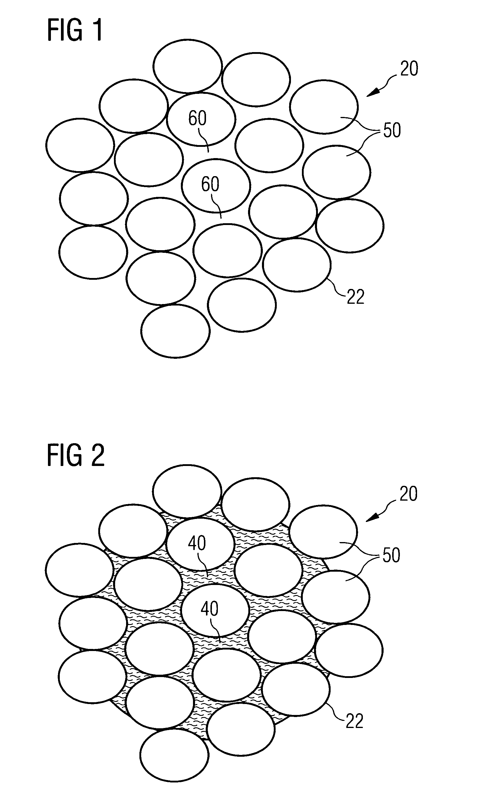
[0120]FIG. 8 shows an SEM of the cross section of the untreated yarn 20 of FIG. 7 comprised of multiple fibers 50 on a larger scale. Between the fibers 50 of the yarn 20 and within the cross-section of the yarn 20 there are several voids 60 of different sizes.

[0121]The f...

example 2

[0134]An untreated fabric as described in example 1 was used. The fabric was laminated to a waterproof and water-vapor permeable barrier layer using a standard lamination process. A porous membrane made of ePTFE was used as barrier layer 90. The membrane Was manufactured according to U.S. Pat. Nos. 3,953,566 and 4,187,390 and was coated with a continuous layer of water vapor permeable hydrophilic polyurethane as described in U.S. Pat. No. 4,194,041. The resulting membrane will hereinafter be referred as coated ePTFE membrane. To create a two layer laminate the fabric of example 1 was laminated to the ePTFE side of the coated ePTFE membrane using a dot pattern of polyurethane adhesive as described in U.S. Pat. No. 4,532,316. The resultant laminate is a water impermeable, water vapor permeable laminate.

[0135]The laminate was impregnated with a silicone solution SilGel 612 of Wacker Chemie AG having a viscosity of 1000 mPa / s. The same process was used as described in example 1. In the ...


PUM

PropertyMeasurementUnit
Lengthaaaaaaaaaa
Pressureaaaaaaaaaa
Lengthaaaaaaaaaa

Abstract

The present invention provides a fabric and a fabric structure made of yarns with reduced water absorption. The fabric comprises yarns and interstices between the yarns, the interstices between the yarns having an average width of greater than 100 μm. At least one of the yarns is comprised of multiple fibers. Said at least one yarn has voids between the fibers wherein the voids are filled up with a polymer material. The interstices remain open and the size of the interstices is the same as before the treatment. The filling of the voids between the fibers with the polymer material prevents the absorption of water into said voids and therefore leads to reduced water absorption of the fabric. The polymer material is substantially only located within the voids of the yarn and has embedded the fibers within the outer surface of said yarn.

Description

FIELD OF THE INVENTION[0001]The application relates to an improved fabric made of multifilament yarns with a high air-permeability and with reduced water absorption. Furthermore, the application relates to a fabric structure comprising a barrier layer, the fabric structure showing a high air-permeability or high water vapor permeability and reduced water absorption.BACKGROUND OF THE INVENTION[0002]Fabrics for clothing with a reduced ability to absorb water after contact with it are desired. Yarns for fabrics may be comprised of multi-filaments or staple fibers. Such yarns in the form of fiber / filament bundles comprise voids between the fibers / filaments. In case the yarn comes into contact with a liquid like water, most of the liquid wicks into the voids of the yarn. This wicking process results in a textile that will be wet, heavy and is very often difficult to dry.[0003]One possibility to overcome this drawback is providing the fabrics with hydrophobic finishes usually based on flu...

Claims


Application Information

Patent Timeline
IPC IPC(8): B32B5/24B32B5/02B32B27/04B32B5/00B32B7/14B05D3/02
CPCB32B5/02Y10T428/24851D06M11/44D06M11/45D06M11/47D06M11/68D06M15/244D06M15/564D06M15/643B32B5/28D06N2211/10D06N3/0006D06N2209/128D06N2209/125D06N3/0022D06N3/047D06N3/128D06N3/14D06N2209/123B32B5/245B32B5/26B32B2262/0276B32B2262/06B32B2262/14B32B2266/0235B32B2307/7244B32B2307/7246B32B2307/7265B32B27/12Y10T442/2369Y10T428/249981Y10T442/2139Y10T442/2893Y10T442/2885Y10T442/2631Y10T428/249962Y10T442/2762Y10T442/2664Y10T442/2861Y10T428/249953Y10T442/2672Y10T442/2418Y10T442/2656Y10T442/20Y10T442/2352Y10T442/2164Y10T442/2869Y10T442/291Y10T442/2607Y10T442/2598
Inventor STUEBIGER, WERNER
Owner STUEBIGER WERNER
Why Eureka
Try Eureka