Laser scanner, laser scanner measuring system, calibration method for laser scanner measuring system and target for calibration

a laser scanner and laser scanner technology, applied in the direction of distance measurement, optical radiation measurement, instruments, etc., can solve the problems of difficult identification of measured points, measurement errors may occur, laser scanners with individual differences, etc., to achieve easy identification, easy association, and easy detection

Active Publication Date: 2010-10-07
KK TOPCON
View PDF14 Cites 57 Cited by
  • Summary
  • Abstract
  • Description
  • Claims
  • Application Information

AI Technical Summary

Benefits of technology

[0014]The present invention provides a laser scanner, comprising a light emitting element for emitting a pulsed laser beam, a rotary projecting unit for projecting the pulsed laser beam for scanning, a distance measuring unit, which has a distance measuring light receiving unit, for measuring a distance by receiving a reflection light from an object to be measured, and a control unit for driving and controlling the light emitting element and the distance measuring unit, wherein the control unit judges the object to be measured by detecting a level of light quantity of a reflected pulsed laser beam as received by the distance measuring light receiving unit. As a result, an object to be measured can be identified in simple manner, and the measured distance can be easily associated with the object to be measured.
[0015]Also, the present invention provides a laser scanner measuring system, comprising a laser scanner and a calibration target, wherein the laser scanner comprises a light emitting element for emitting a pulsed laser beam, a rotary projecting unit for projecting the pulsed laser beam for scanning, a distance measuring unit, which has a distance measuring light receiving unit, for measuring a distance by receiving a reflection light from an object to be measured, and a control unit for driving and controlling the light emitting element and the distance measuring unit, and wherein the calibration target has a reflection sector with a known shape and with high reflectance, wherein the control unit judges a reflected pulsed laser beam from the reflection sector as received by the distance measuring light receiving unit by detecting a level of light quantity and determines a center position of the reflection sector based on the result of judgment. As a result, an object to be measured can be identified in simple manner, and the measured distance can be easily associated with the object to be measured.
[0016]Further, the present invention provides a laser scanner measuring system, wherein the calibration target is installed at a position to be measured, and by measuring a center position of the calibration target by the laser scanner, the position to be measured is determined. As a result, it is possible to perform measurement on a specific point where measurement cannot be carried out by a conventional type laser scanner.
[0017]Also, the present invention provides a calibration method for calibrating a laser scanner measuring system, which has a laser scanner and a calibration target, wherein the laser scanner comprises a light emitting element for emitting a pulsed laser beam, a rotary projecting unit for projecting the pulsed laser beam for scanning, a distance measuring unit, which has a distance measuring light receiving unit, for measuring a distance by receiving a reflection light from an object to be measured, and a control unit for driving and controlling the light emitting element and the distance measuring unit, and wherein the calibration target has a reflection sector with a known shape and with high reflectance and is installed at a known position, comprising a step for judging a reflected pulsed laser beam from the reflection sector as received by the distance measuring light receiving unit by detecting a level of light quantity, a step for determi

Problems solved by technology

On the other hand, it is very difficult to identify the measured points.
Also, the laser scanner has individual differences caused by error in a manufacturing process, and by error in a process of mounting.
Further, when there is environmental change such as temperature change during a process of measurement, a mea

Method used


Image

  • Laser scanner, laser scanner measuring system, calibration method for laser scanner measuring system and target for calibration
  • Laser scanner, laser scanner measuring system, calibration method for laser scanner measuring system and target for calibration
  • Laser scanner, laser scanner measuring system, calibration method for laser scanner measuring system and target for calibration

Examples


Embodiment Construction

[0031]Description will be given below on the best aspect for carrying out the invention by referring to the attached drawings.

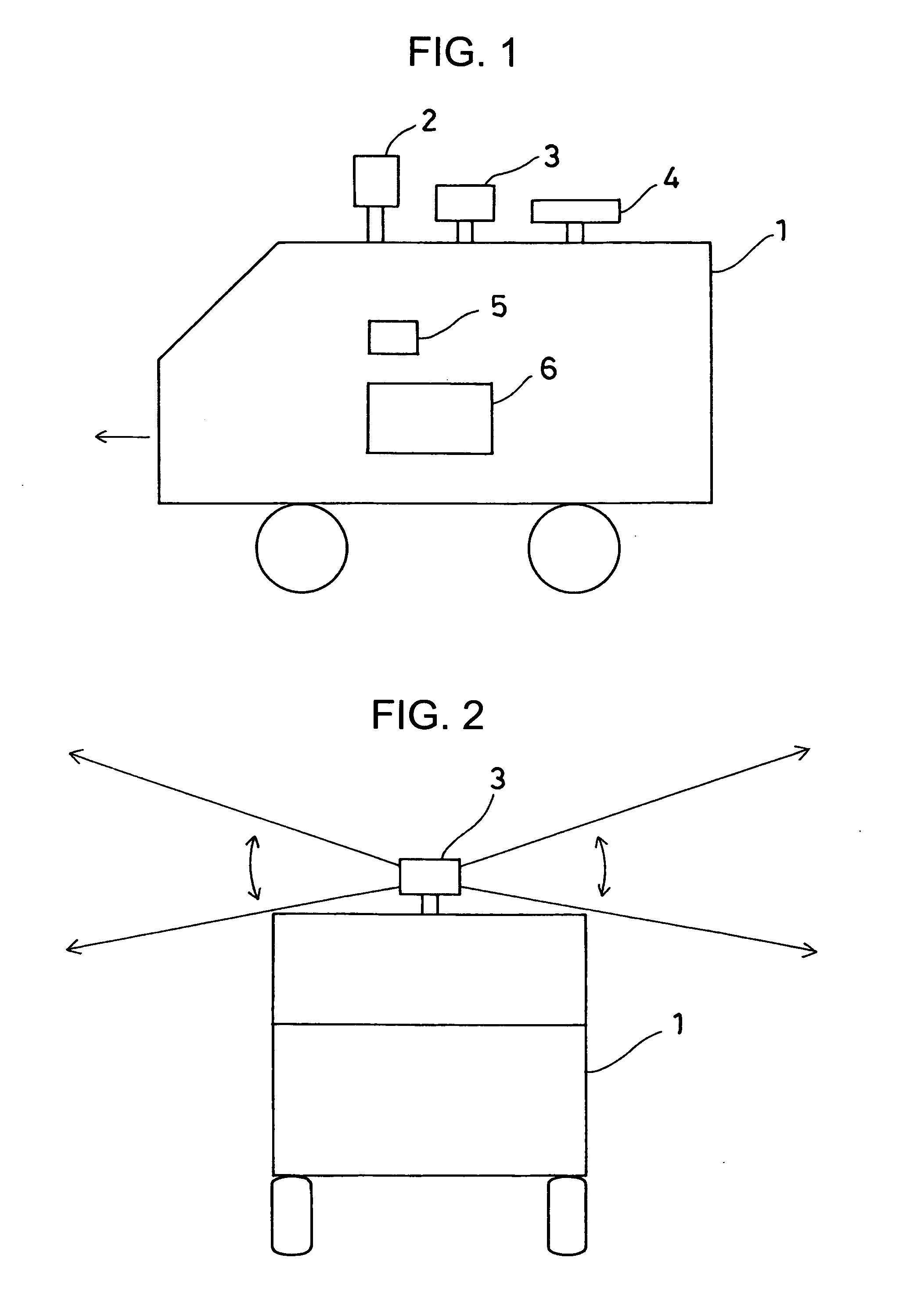
[0032]FIG. 1 and FIG. 2 each represents general features of a laser scanner measuring system according to the present invention.

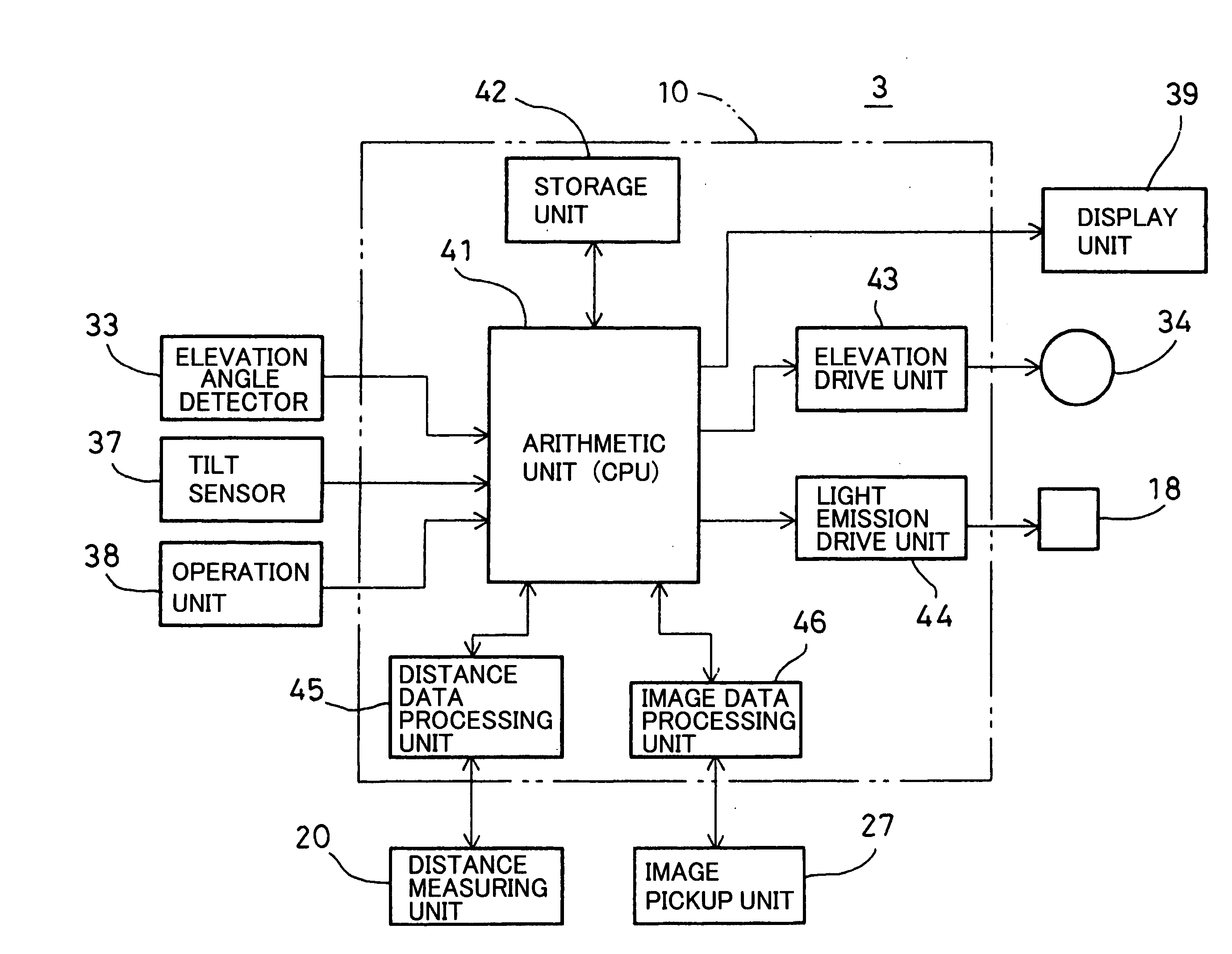
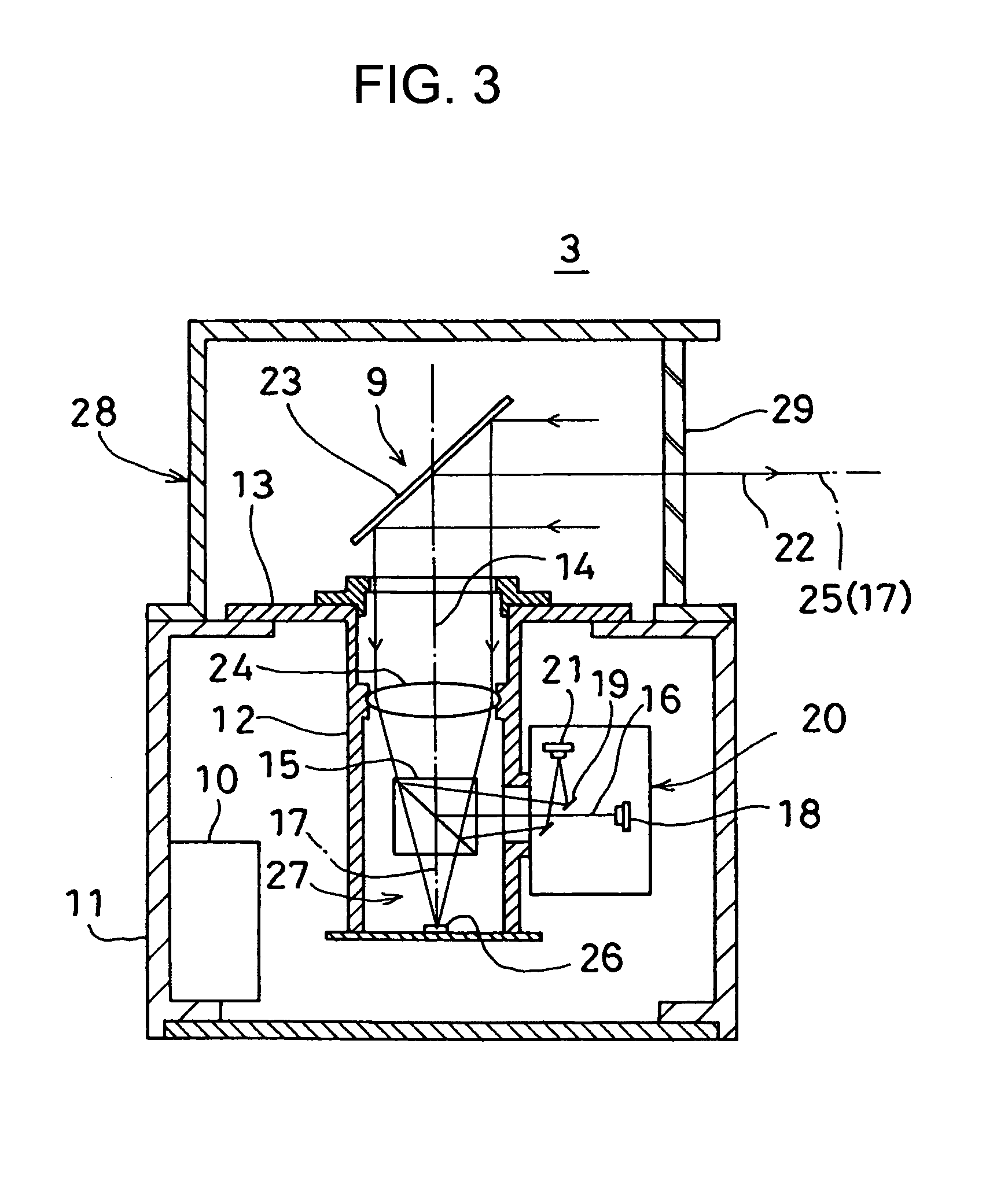
[0033]Reference numeral 1 denotes a mobile device such as a vehicle. On the mobile device 1, there are provided devices necessary for acquiring three-dimensional data, i.e. all-azimuth camera 2, a laser scanner 3, a GPS 4, an inertia measuring sensor 5, and a control device 6.

[0034]The all-azimuth camera 2 is used to pick up images of sceneries in forward direction and in lateral direction with respect to a driving direction of the mobile device 1 and to output the results as image data. The laser scanner 3 is to project a pulsed laser beam in a direction perpendicularly crossing the driving direction of the vehicle and to acquire a point group data by projecting the pulsed laser beam in vertical direction for scanning. The GPS 4 is ...


PUM


Abstract

According to the present invention, a laser scanner measuring system, which has a laser scanner and a calibration target, wherein the laser scanner comprises a light emitting element for emitting a pulsed laser beam, a rotary projecting unit for projecting the pulsed laser beam for scanning, a distance measuring unit, which has a distance measuring light receiving unit, for measuring a distance by receiving a reflection light from an object to be measured, and a control unit for driving and controlling the light emitting element and the distance measuring unit, and wherein the calibration target has a reflection sector with a known shape and with high reflectance and is installed at a known position, comprising a step for judging a reflected pulsed laser beam from the reflection sector as received by the distance measuring light receiving unit by detecting a level of light quantity, a step for determining a center position of the reflection sector based on the result of the judgment, and a step for calibrating the laser scanner measuring system based on the determined center position and on the known position.

Description

BACKGROUND OF THE INVENTION[0001]The present invention relates to a laser scanner and a laser scanner measuring system for acquiring three-dimensional data by using GPS (Global Positioning System). The invention also relates to a target for calibration used for the laser scanner measuring system and relates to a calibration method for the laser scanner measuring system.[0002]In recent years, with a widespread use of car navigation system and other related technique, there are increasing demands to have three-dimensional position data and further, three-dimensional image data, which can be used as map data. As a surveying instrument to acquire such type of three-dimensional data, a laser scanner measuring system using GPS and IMU (inertial measuring unit) is currently used. By using a laser scanner, it is possible to acquire an enormous amount of three-dimensional data within short time. Further, a position of the laser scanner is measured by using GPS and also a posture of the laser...

Claims


Application Information

Patent Timeline
IPC IPC(8): G01C25/00G01C3/08G01J1/10G06F19/00G01S7/497G01S17/06G01S17/88G01S17/89
CPCG01S7/4812G01S7/497G01S17/42G01S17/89
Inventor OGAWA, KAZUHIROSHIBUYA, HIROTOYAMAGUCHI, SHIGEYUKIMIYOSHI, RYOUSUKESASAKI, YOUKONNO, HIROYUKIDEBOER, JEFFREY ROBERT
Owner KK TOPCON
Why Eureka
Try Eureka