System timeline execution model development methodology for large distributed real-time embedded systems

Inactive Publication Date: 2010-10-07
BAE SYSTEMS LAND & ARMAMENTS LP
View PDF17 Cites 5 Cited by
  • Summary
  • Abstract
  • Description
  • Claims
  • Application Information

AI Technical Summary

Benefits of technology

[0008]The present invention is a project management tool for the efficient completion of complex development projects. The System Timeline Execution Model (STEM) methodology for system timeline analysis provides a clear understanding of the sequencing and parallelism of the system events in a large complex software weapon system such as the Crusader Field

Problems solved by technology

The management of resources for the efficient completion of complex engineering and software projects has long been a challenge to the project participants and management due to the magnitude of tasks to be accomplished.
This approach, however, does very little to optimally allocate limited resources across a weapon system design, and objective characteristics of an operational design often exceed program constraints.
In addition to sub-optimized designs, the top-down approach often leads to misallocated developmen

Method used


Image

  • System timeline execution model development methodology for large distributed real-time embedded systems
  • System timeline execution model development methodology for large distributed real-time embedded systems
  • System timeline execution model development methodology for large distributed real-time embedded systems

Examples


Embodiment Construction

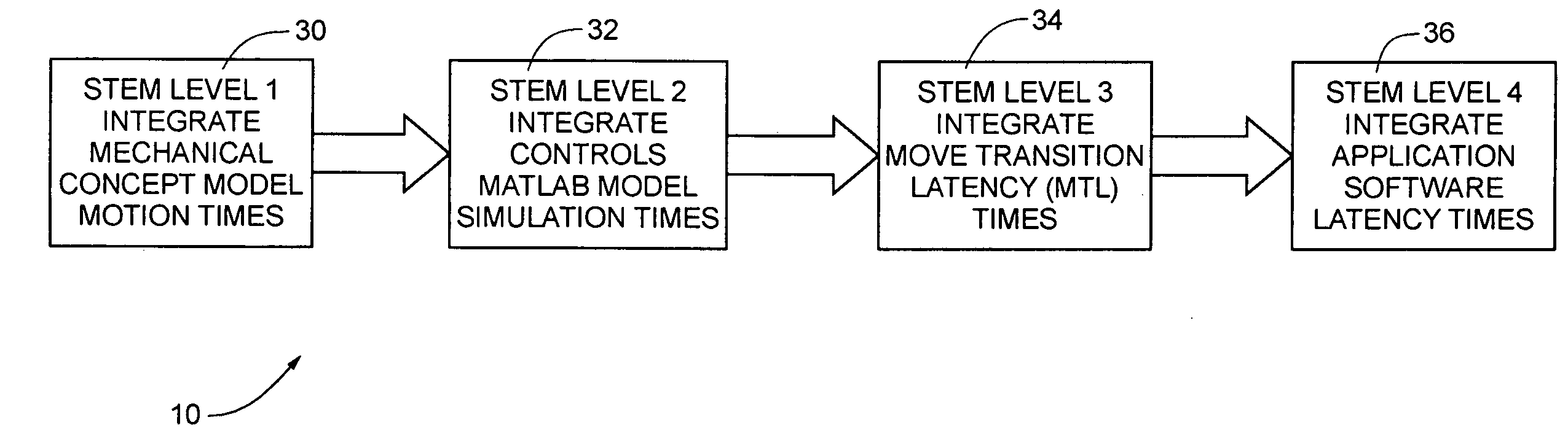
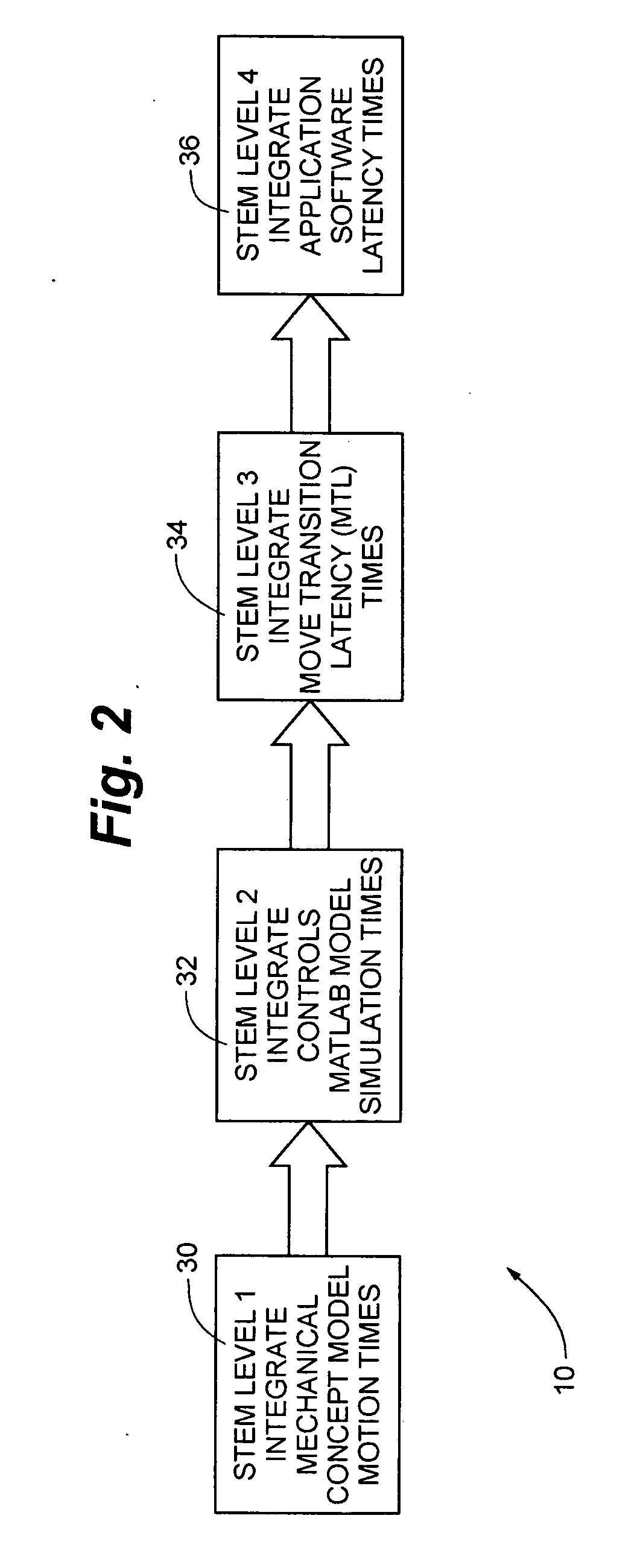
[0026]Generally, product development requires the design to meet performance and timing goals proposed by the customer. One method of influencing and monitoring how well the designs are being developed with regards to meeting the timing requirements is through system timeline analysis. A system timeline represents a sequence of system events that must take place during a given period of time as defined by the customer requirements. System timelines provide a high level view of the computing-mechanical interactions and sequencing that must occur in order for a time requirement to be met. Within the system timeline, significant system events known as “synch points” need to be defined and suitable time budgets for these synch points need to be developed to drive the efforts of various product development teams.

[0027]A solution to making the system timelines both understandable to all project members and valuable to the overall project is the use of state diagrams. The term “state diagr...


PUM


Abstract

The present invention is a project management tool uniquely suited to define and develop significant system events that can be effectively used as system test points to measure the performance and determine whether the system under design is meeting key design requirements. This methodology utilizes Synch Points in a state diagram to provide a directed graph notation and to generate a system timeline execution model automatically. The state diagram provides an improved means to decompose system event times into mechanical motion times, move transition latency times, and application software latency times. The system timeline execution model data is fed into a simulation engine to verify that the system timeline execution model is executable and confirms the dependencies are complete and accurate.

Description

RELATED APPLICATION[0001]The present application claims the benefit of U.S. Provisional Application No. 60 / 720,574 filed Sep. 26, 2005, which is incorporated herein in its entirety by reference.GOVERNMENT INTEREST[0002]The invention was made under a contract with an agency of the U.S. Government. The name of the U.S. Government agency is the United States Army and the Government contract numbers are DAAE30-95-C-009 and FCS No. 4EC2090.FIELD OF THE INVENTION[0003]The present invention relates generally to product management and in particular a methodology for providing a common basis for multiple product development teams to monitor and regulate product development.BACKGROUND OF THE INVENTION[0004]The management of resources for the efficient completion of complex engineering and software projects has long been a challenge to the project participants and management due to the magnitude of tasks to be accomplished. For example, the development of complex military equipment traditional...

Claims


Application Information

Patent Timeline
IPC IPC(8): G06Q10/00
CPCG06Q10/06G06Q10/101G06Q10/10
Inventor IYER, BALASUBRAMANIAN K.LARSON, PHYLLIS J.
Owner BAE SYSTEMS LAND & ARMAMENTS LP
Why Eureka
Try Eureka