Method and System for Migrating Processes Between Virtual Machines

a virtual machine and process technology, applied in the field of methods and systems for migrating processes between virtual machines, can solve the problems that the migration of entire virtual machines from one server to another server cannot alleviate excessive workload, and the current migration techniques do not adequately resolve the increased workload within a single operating system, so as to improve hardware resource utilization.

Active Publication Date: 2010-10-07
VMWARE INC
View PDF14 Cites 247 Cited by
  • Summary
  • Abstract
  • Description
  • Claims
  • Application Information

AI Technical Summary

Benefits of technology

[0003]One or more embodiments of the present invention provide a method and system to migrate individual user-level processes running within a particular virtual machine on one server to another server. The migrated user-level processes are placed in a virtual machine on the other server that replicates the original virtual machine such that the user-level processes continue to run as if they were still running in the original virtual machine, for exam

Problems solved by technology

However, migration of entire virtual machines from one server to another server cannot alleviate excessive workloads that occur within a single virtual machine.
Current migration techniques do not adequately resolve the in

Method used


Image

  • Method and System for Migrating Processes Between Virtual Machines
  • Method and System for Migrating Processes Between Virtual Machines
  • Method and System for Migrating Processes Between Virtual Machines

Examples


first embodiment

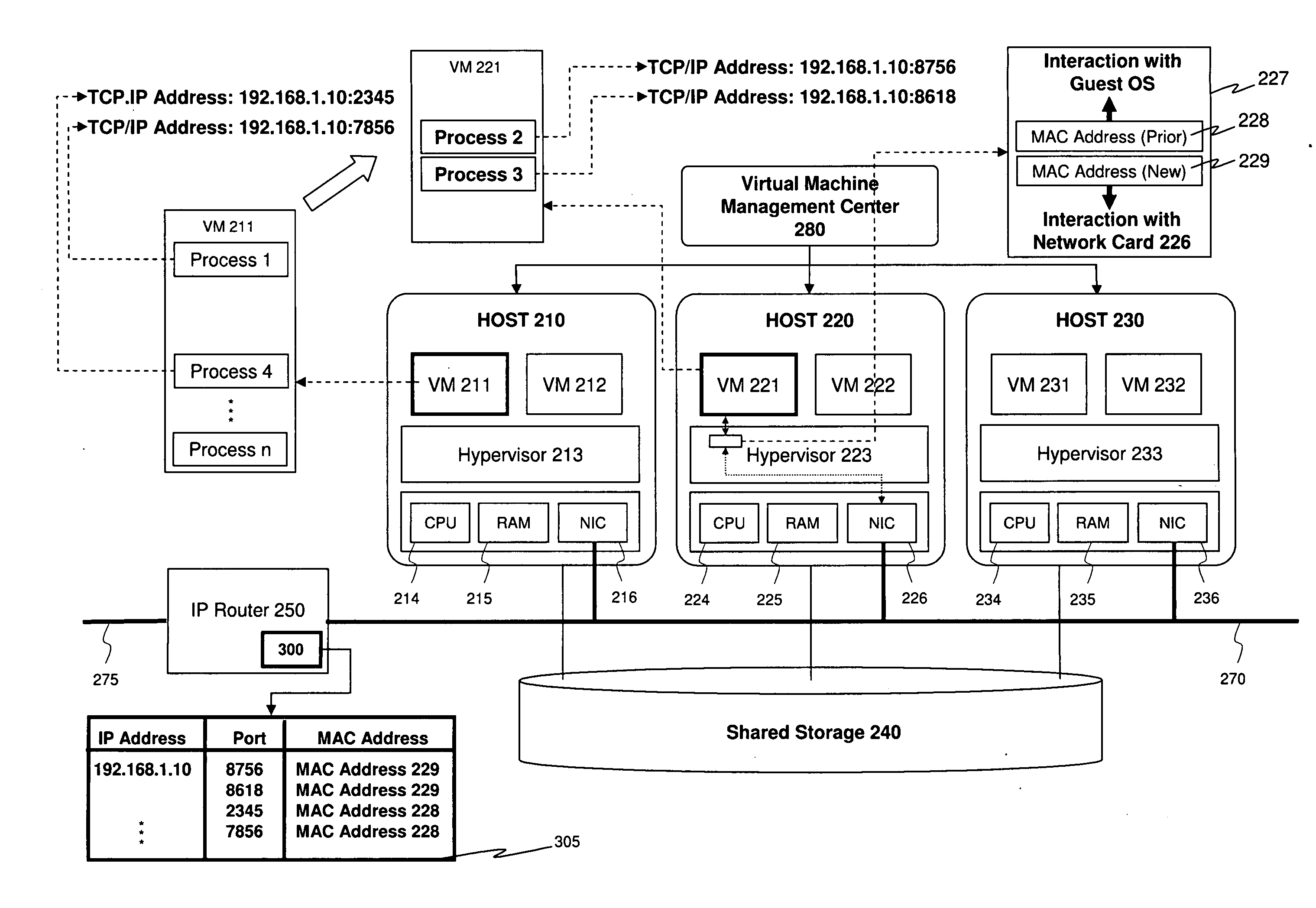
[0021]FIG. 3 depicts a virtual infrastructure according to the invention. As discussed in the foregoing, VM 211 and VM 221 share the same IP address and, for exemplary purposes, Processes 2 and 3 each utilize the same network and have established TCP connections. As shown in FIG. 3, virtual router component 300 is embedded in IP router 250, and virtual router component 300 is used to route IP packets that have as their destination IP address the IP address shared by VM 211 and VM 221. As further shown in FIG. 3, virtual router component 300 maintains routing table 305 that maps TCP / IP address-port combinations to virtual MAC addresses. In accordance with one or more embodiments of the present invention, upon completion of VM migration, virtual management center 280: (a) queries VMs 211 and 221 to obtain the TCP / IP address-port number combinations used by any established TCP / IP connections running on the VMs; and (b) instructs virtual router component 300 to insert mappings from such...

second embodiment

[0026]FIG. 5 depict a virtual infrastructure according to the invention. Rather than having a virtual router component as part of IP router 250 (as shown in FIG. 3), in FIG. 5, a virtual router software component 500 is embedded in the hypervisor (i.e., hypervisor 213) of host 210 running source VM 211 to properly route IP packets having as their destination IP address as the IP address shared by VM 211 and VM 221. Virtual router software component 500 is situated within the hypervisor between the virtual NIC of VM 211 and the NIC driver (including the virtual bridge) of NIC 216. Virtual router software component 500 also maintains a routing table (i.e., routing table 505) that maps TCP / IP address-port combinations to virtual MAC addresses. Upon completion of VM migration, virtual management center 280: (a) queries VMs 211 and 221 to obtain the TCP / IP address-port number combinations used by established TCP / IP connections running on the VMs; and (b) instructs virtual router software...


PUM


Abstract

One or more processes are offloaded from one virtual machine running on one host computer to another virtual machine running on another host computer so that load balancing can be performed on a per process level and physical servers supporting the virtual machines can be more optimally utilized. Migrating one or more processes from a virtual machine running on a first host computer to a second host computer includes replicating the virtual machine on the second host computer, terminating the migrated processes from the virtual machine running on the first host computer, and terminating all user-level processes running on the replicated virtual machine other than the migrated processes.

Description

BACKGROUND OF THE INVENTION[0001]Virtualization technologies known as server based computing (SBC) and virtual desktop infrastructure (VDI) enable organizations to replace traditional personal computers (PCs) with instances of desktops that are hosted on virtual machines running on servers in a data center. A thin client installed on a user's terminal remotely connects to operating remote sessions that present a graphical portion of an application or desktop to the user on the terminal. Typically SBC systems are designed to host multiple users per operating system and VDI systems are designed to host one user per session. VDI uses multiple virtual machines, each simultaneously running an operating system, to host multiple running operating systems, thereby allowing multiple users to share a single physical server machine. Both types of systems are designed to target a large number of users where multiple servers are required. Both types of systems utilize a “connection broker” that ...

Claims


Application Information

Patent Timeline
IPC IPC(8): G06F9/46G06F15/16G06F9/455
CPCG06F9/4856G06F9/45558G06F2009/4557G06F9/5083
Inventor CLARK, JONATHAN
Owner VMWARE INC
Why Eureka
Try Eureka