Trace synchronization

a trace and data synchronization technology, applied in the direction of instruments, specific program execution arrangements, program control, etc., can solve the problems of data loss conditions within the trace monitoring circuitry of the data processing apparatus, and the amount of trace data generated at a particular time may become large, and achieve the effect of little additional hardware cos

Active Publication Date: 2010-10-07
ARM LTD
View PDF18 Cites 55 Cited by
  • Summary
  • Abstract
  • Description
  • Claims
  • Application Information

AI Technical Summary

Benefits of technology

[0033]This problem can be addressed by arranging for the requesting circuitry of at least one trace handling circuit to issue a global synchronization request to a plurality of trace sources. For each of the trace data sources, the controller initiates the synchronization marker generator in response to receipt of the global synchronization request. Global trace synchronization means that all trace data sources would be synchronized together. In the example explained above, synchronization of both trace streams could be requested every 1000 bytes of data captured by the trace handling circuit. This should ensure that for a 4000 byte buffer there will be four synchronization points in each of the captured trace streams. Since synchronization is controlled globally by the trace handling circuits (not by individual trace data sources), there is no risk of accidentally losing trace data because synchronization data did not get captured. Also, there is no need to try to predict trace bandwidth requirements of multiple sources in advance.
[0034]It will be appreciated that different methods could be used to distribute the global synchronization requests to the plurality of trace data sources. However, when the at least one trace handling circuit receives trace data from the plurality of trace data sources via respective trace data paths, it is particularly useful for the requesting circuitry of the at least one trace handling circuit to issue the global synchronization request to the plurality of trace data sources via those same trace data paths. The trace data paths could be part of a trace bus infrastructure. Since the trace data paths will already have been configured at run-time to transmit the trace data from

Problems solved by technology

Where multiple trace data sources are used to generate trace data corresponding to multiple respective elements of the data processing apparatus, the amount of trace data generated at a particular time may

Method used


Image

  • Trace synchronization
  • Trace synchronization
  • Trace synchronization

Examples


Embodiment Construction

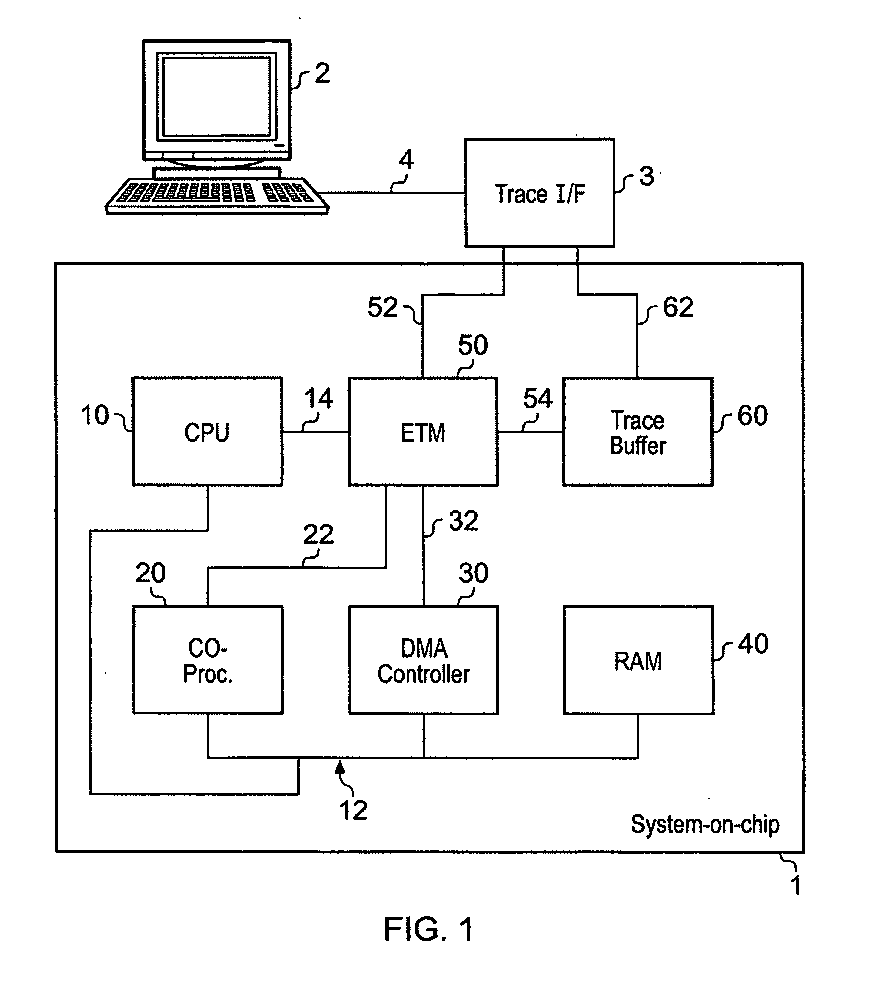
[0079]Referring to FIG. 1, an integrated circuit 1, in this case a system-on-chip circuit, is illustrated. The integrated circuit 1- is coupled to a trace analysis apparatus 2 via a trace interface 3. The trace analysis apparatus may be a general purpose data processing apparatus provided with the necessary software and hardware to connect to the integrated circuit 1 via the trace interface 3, and to perform the required analysis on trace data output from the integrated circuit 1. Trace data generated by the integrated circuit 1 is provided to the trace analysis apparatus 2 via the trace interface 3, and a trace information line 4 connecting the trace analysis apparatus 2 to the trace interface 3.

[0080]The integrated circuit 1 comprises a central processing unit 10, a coprocessor 20, a DMA controller 30, and a memory 40, in this case a random access memory (RAM). The central processing unit 10, the coprocessor 20, the DMA controller 30 and the memory 40 are coupled together via a bu...


PUM


Abstract

A data processing apparatus having one or more trace data sources is provided in which the trace data sources operate to generate respective streams of trace data. At least one of said trace data sources comprises a trace data generator responsive to activity in monitored circuitry to generate trace data representing said activity. A synchronization marker generator is coupled to the trace data generator and operates to generate a synchronization marker and insert the synchronization marker into the trace data stream. The synchronization marker identifies a synchronization position in the trace data stream. A controller is coupled to the synchronization marker generator, and operates to initiate the synchronization marker generator to generate and insert a synchronization marker into the trace data stream. The controller controls initiation in dependence on behavior of the data processing apparatus downstream of the trace data generator with respect to trace data flow. In this way, the downstream behavior of the data processing apparatus can be made to influence the rate and timing of insertion of synchronization markers into a trace data stream, thereby reducing the likelihood of the volume of trace data resulting in an overflow condition in the downstream circuitry.

Description

BACKGROUND OF THE INVENTION[0001]1. Field of the Invention[0002]This invention relates to trace synchronization. More particularly, this invention relates to a data processing apparatus and a data processing method which control the insertion of synchronization markers into a trace data stream to enable the synchronization of the trace data.[0003]2. Description of the Prior Art[0004]In a data processing apparatus, there are two main methods of facilitating debugging. The first method is to use debugging techniques such as setting breakpoints to halt code execution at a specific activity and to use a debug connection between the data processing apparatus and an external debugging apparatus to examine the status of the data processing apparatus at the breakpoint. The second method is to use trace monitoring to collect from the data processing apparatus, in real time, data representing instruction execution and / or data transfers, and to deliver the data to a trace analysis apparatus. O...

Claims


Application Information

Patent Timeline
IPC IPC(8): G06F9/44
CPCG06F11/348G06F11/3648G06F11/3636G06F11/3632
Inventor HORLEY, JOHN MICHAELSWAINE, ANDREW BROOKFIELDHOULIHANE, THOMAS SEANWOODHOUSE, SHELDON JAMESWILLIAMS, MICHAEL JOHN
Owner ARM LTD
Why Eureka
Try Eureka