
Replacement and urging device for the bucket teeth of an engineering construction machine

a technology of engineering construction machine and urging device, which is applied in the direction of soil shifting machine/dredger, construction, etc., can solve the problems of clogging the pin, increasing the difficulty of replacement, and inconvenience in replacement, and achieve the effect of quick removal

Inactive Publication Date: 2010-10-14
KO JUNG CHING
View PDF16 Cites 22 Cited by
  • Summary
  • Abstract
  • Description
  • Claims
  • Application Information

AI Technical Summary

Benefits of technology

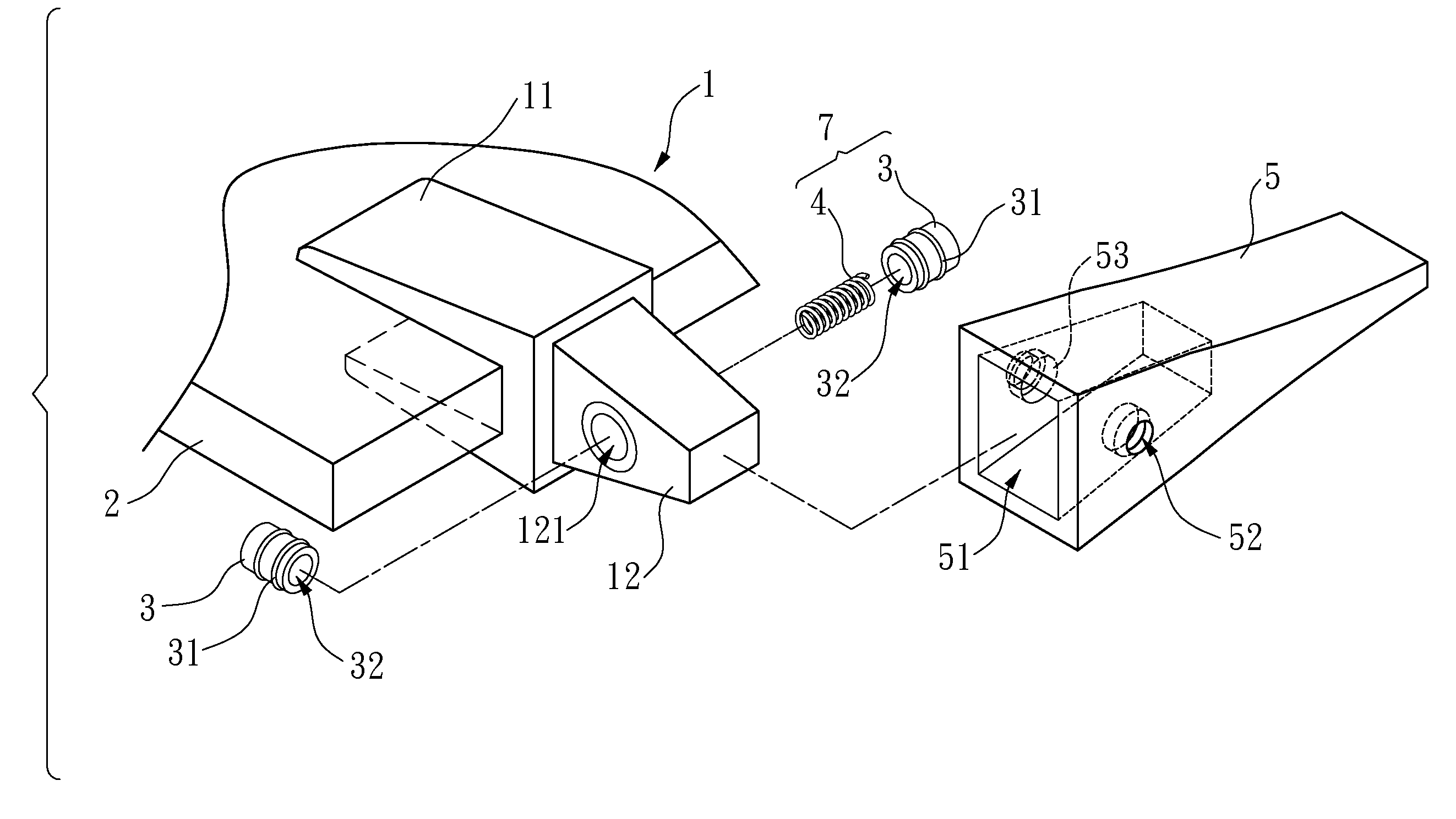
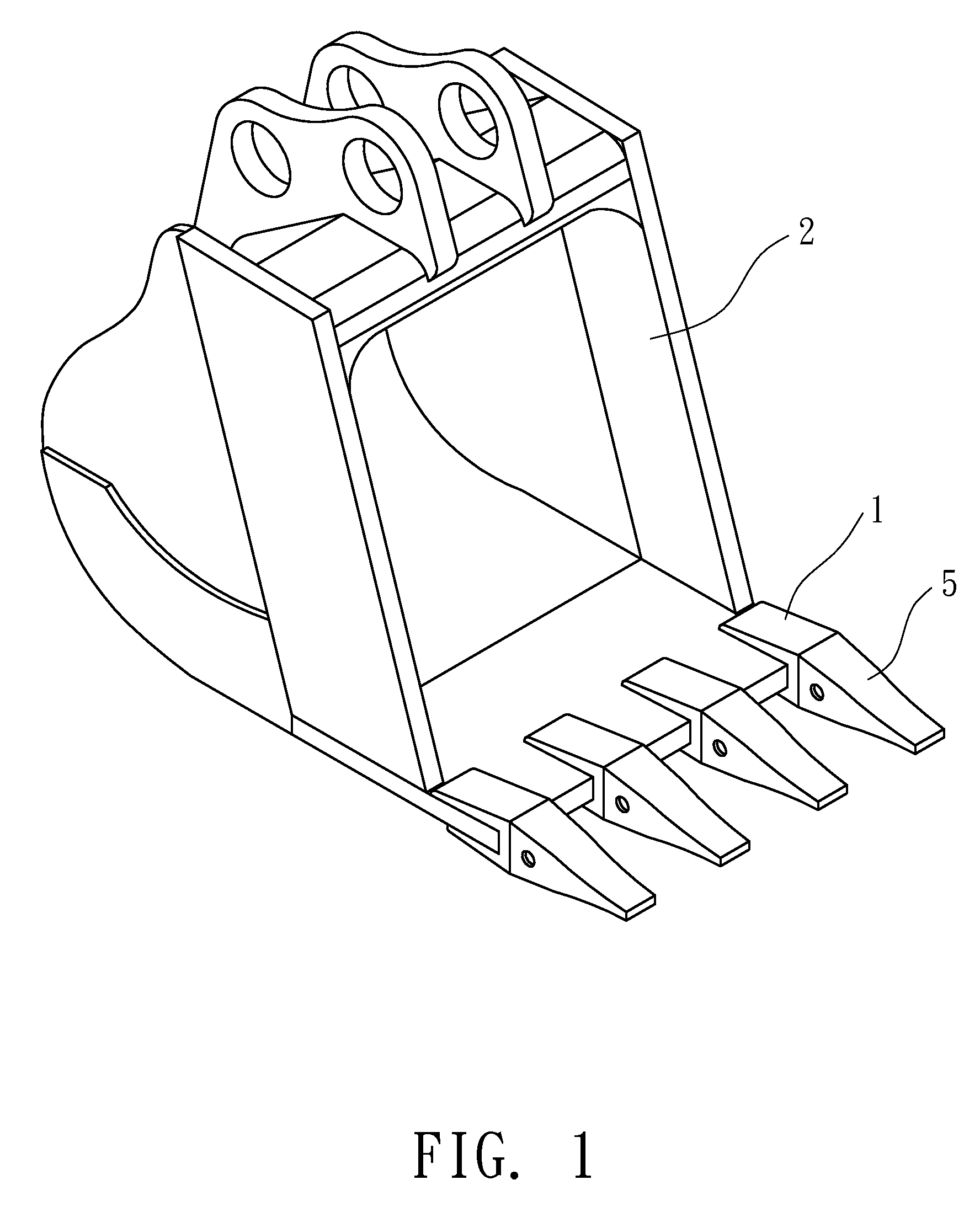
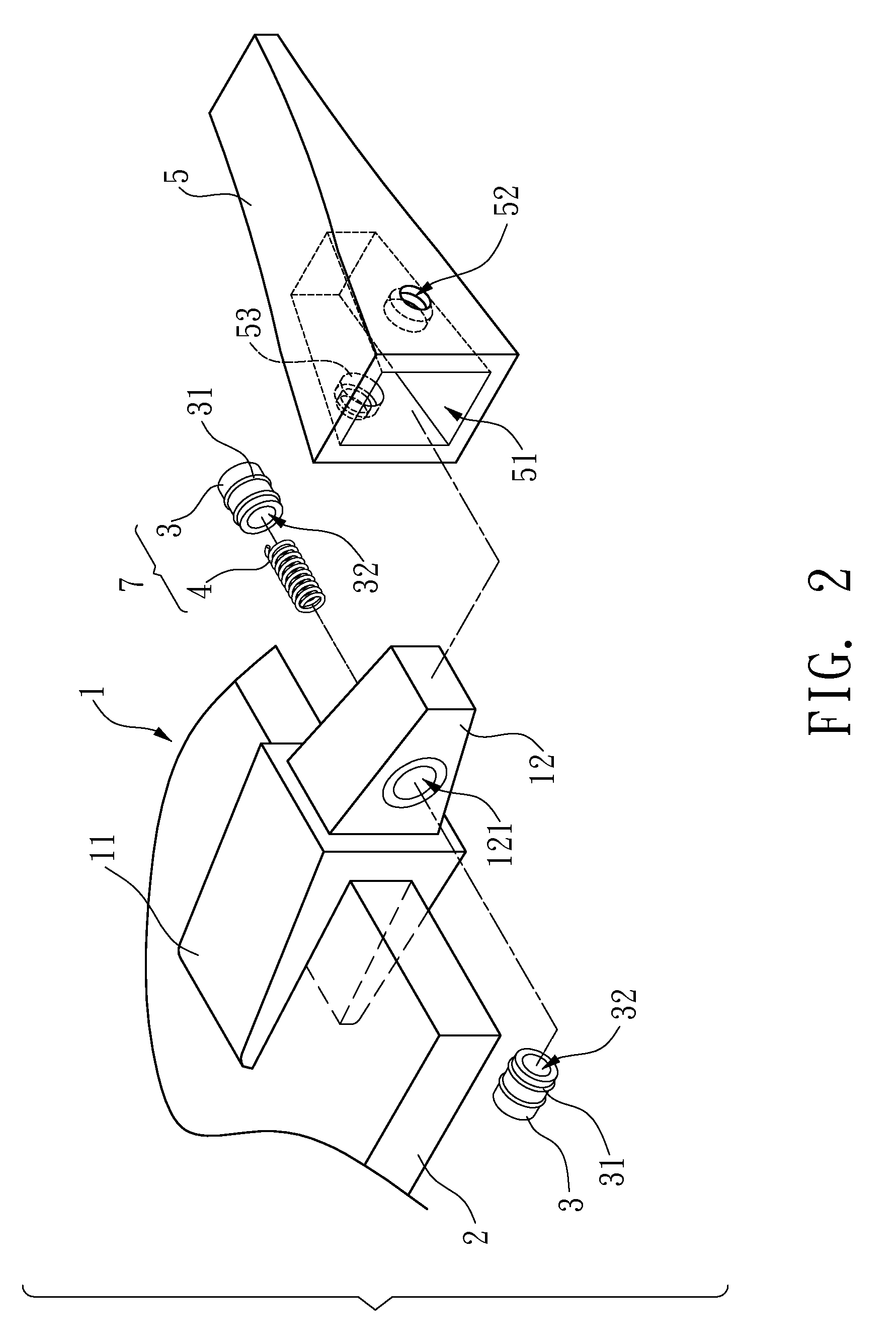
[0012]An objective of the invention is to solve the above-mentioned problems by providing a replacement and urging device whose bucket teeth can be quickly removed and assembled. It is convenient to replace the bucket teeth on the bucket.
[0013]Another objective of the invention is to prevent the adaptor and bucket teeth from developing a shifting gap during uses. This prevents the pins from being hit by the bucket teeth and breaking.

Problems solved by technology

1. As seen in FIGS. 15 and 16, the spacing between the bucket teeth 9 of the bucket is limited. When the pin 92 is hit into the predetermined position of the first through hole 901, there is no sufficient hitting distance and appropriate hitting angle. Therefore, the hammer has to be disposed inside a tiny space for hitting. Only after the pin 92 penetrates via the second through hole 911 into an appropriate depth of fee first through hole 901 car the user hold the hammer 93 at an angle and further hit the pin 92 with the help of an auxiliary hitting rod. The pin 92 is then completely disposed and positioned between the first through hole 901 and the second through holes 911 of the adaptor 90 and the bucket teeth 91. In this case, the local structure of the pin 92 may be deformed or the entire structure is curved because of the hitting. This causes troubles in replacing the bucket teeth 9 in the future.
2. When the bucket performs a digging process, objects inevitably get into the gap between the pin 92 and the first through hole 901 and the second through holes 911. If the object is a pebble or metal block, it may lock the pin 92 in the through holes 901, 911. If the object is mud, then it may clog the pin 92 in the through holes 901, 911. Therefore, when taking die pin 92 off of the through holes 901, 911, one has to remove those objects first. In the worst case, one has to destroy the bucket teeth 9 (e.g., cutting the bucket teeth 9 using a hydrogen flare).
3. FIG. 17 is a schematic view of taking off the pin 92. A tube 95 goes through the first through hole 901 of the adaptor 90 on the outermost side. One end of the tube 95 urges against the pin 92 to be taken off. The user then uses a hammer 93 to hit so that the pin 92 escapes from the C-shaped buckle 902, departing from the first through hole 901 and the second through holes 911. The reason for doing this is because the space between the bucket teeth 9 is limited. The hitting strength of the hammer 93 has to be such that the pin 92 escapes from the C-shaped buckle 902. This causes inconvenience in replacements. Moreover, when the pin 92 is locked or clogged by objects inside the through holes 901, 911 and the C-shaped buckle 902, it becomes even more difficult.
4. Please refer to FIGS. 18 and 19. After the adaptor 90 and the bucket teeth 91 are assembled, there is still a gap A between them. There is also a gap between the second through holes 911 and the pin 92. Therefore, when the bucket teeth 91 urges against the adaptor 90 during a digging process, the two ends of the pin 92 protruding from the first through hole 901 are not directly hit by the bucket teeth 91 because the gap 8 is larger than the gap A.
Besides, the hitting strength is larger for a larger gap, causing more damages to the adaptor 90 and the bucket teeth 91.
In addition to causing troubles in digging, the bucket teeth 91 may even hurt somebody if it fells from a high, place.
The replacement process for the conventional bucket teeth 9 is very inconvenient.

Method used


Image

  • Replacement and urging device for the bucket teeth of an engineering construction machine
  • Replacement and urging device for the bucket teeth of an engineering construction machine
  • Replacement and urging device for the bucket teeth of an engineering construction machine

Examples


fourth embodiment

[0056]Please refer to FIG. 8 for the invention. The bucket teeth 5 has an inner guiding angle 55 on the side that the second through holes 52 open towards the slot 51. The end of each of the stopping posts 3 protruding from the first through hole 121 has an outer guiding angle 33 towards the fixing part 11. The outer guiding angle 33 attaches the bucket teeth 5 to the inner guiding angle 55 of the second through hole 52. The depth of the outer guiding angle 33 is smaller than the inner guiding angle 55. This keeps a gap so that the adaptor 1 and the bucket teeth 5 do not have collisions.

[0057]FIG. 9 shows that the outer guiding angle 33 of the two stopping posts 33 initially urges against the inner guiding angle 55 of the bucket teeth 5 when the bucket teeth 5 is mounted on the adaptor f. As shown in the drawing, the adaptor 1 and the bucket teeth 5 are urged by the two stopping posts 3. Therefore, there is no sliding gap.

[0058]However, as shown in FIGS. 10 to 12, when the bucket te...

fifth embodiment

[0061]Please refer to FIG. 13 for the invention. Each of the stopping posts 4 protrudes from one end of the first, through hole 121. The other side of the outer guiding angle 33 has another corresponding outer guiding angle 33.


PUM


Abstract

A replacement and urging device for the bucket teeth of an engineering construction machine is disclosed. An adaptor is mounted with a bucket tooth. A first through hole holes horizontally through the adaptor. Both sides of the bucket tooth are formed with a second through hole, respectively. An engaging unit is interposed between the first through hole and the second through hole to slide between them. This enables the bucket tooth to be mounted and positioned on the adaptor. The invention thus prevents the bucket tooth from constantly hitting the adaptor.

Description

BACKGROUND OF THE INVENTION[0001]1. Field of Invention[0002]The invention relates to a replacement and urging device for the bucket teeth of an engineering construction machine and, in particular, to a replacement and urging device for the bucket teeth of an engineering construction machine that fixes the bucket teeth on the adaptor of a bucket to prevent the bucket teeth, from hitting the adaptor repeatedly.[0003]2. Related Art[0004]FIG. 14 shows a conventional excavator bucket tooth structure. A bucket is formed with several equally spaced bucket teeth 9. Each of the bucket teeth 9 includes a adaptor 90 and a bucket teeth 91. The adaptor 90 has a horizontal first through hole 901. The bucket teeth 91 is mounted on the adaptor 90. Both sides of the bucket teeth have respectively a second through, hole 911 corresponding to the first through hole 901 of the adaptor 90. A hammer 93 hits a pin 92 from the second through hole 911 on one side of the bucket teeth 91 into the first through...

Claims


Application Information

Patent Timeline
IPC IPC(8): E02F9/28
CPCE02F9/2841E02F9/2825
Inventor KO, JUNG-CHING
Owner KO JUNG CHING
Learn More