System and Method for Induction Heating of a Soldering Iron

a soldering iron and induction heating technology, applied in the field of soldering irons, can solve the problems of increased heating of the working tip through magnetic loss or hysteresis, and decreased or cessation of joule heating

a soldering iron and induction heating technology, applied in the field of soldering irons, can solve the problems of increased heating of the working tip through magnetic loss or hysteresis, and decreased or cessation of joule heating

US20100258554A1Active Publication Date: 2010-10-14HAKKO CO LTD

Image

  • System and Method for Induction Heating of a Soldering Iron
  • System and Method for Induction Heating of a Soldering Iron
  • System and Method for Induction Heating of a Soldering Iron

Examples


Embodiment Construction

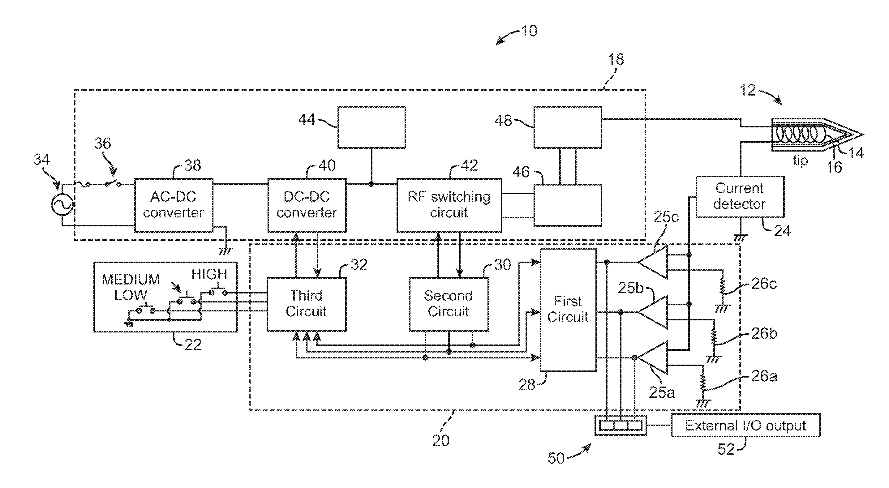
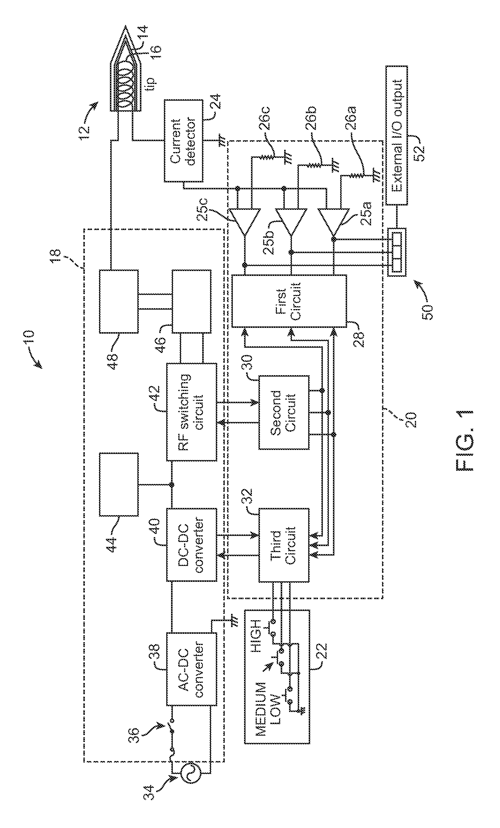
[0014]Referring now in more detail to the exemplary drawings for purposes of illustrating embodiments of the invention, wherein like reference numerals designate corresponding or like elements among the several views, there is shown in FIG. 1 a soldering iron system 10 that utilizes induction heating of a soldering iron tip 12. As will be apparent from the description below, the temperature of the tip can be precisely adapted for various soldering tasks in a convenient and cost-effective manner.

[0015]The tip includes an induction heating portion 14, which may be made of a magnetic alloy, and a coil 16 that produces magnetic flux that induces current in the heating portion 14 when electrical power is delivered to the coil 16. The heating portion 14 may be in the form of a thin layer of ferromagnetic material surrounding the coil 16. It will be appreciated that any tip configuration suitable for induction heating may be used with the present invention. For example, the tip configurati...


PUM

PropertyMeasurementUnit
frequencyaaaaaaaaaa
Tcaaaaaaaaaa
output frequencyaaaaaaaaaa

Abstract

A soldering iron system includes a power assembly that provides power to an induction heater at a variable voltage and a variable frequency. A control assembly adjusts the temperature of the heater in accordance with signals from a current detector coupled to the induction heater and a selection made by the user on an operating level selector.

Description

FIELD OF THE INVENTION[0001]This invention relates generally to soldering irons and, more particularly, to induction heating of soldering irons.BACKGROUND OF THE INVENTION[0002]Electromagnetic induction has been used to heat soldering irons. An advantage of using induction heating is the reduced heat loss of the working tip as compared to indirect methods of heating in which heat from a separate resistance coil heater must be transferred to the working tip. Electrical eddy currents are induced in the working tip of the soldering iron. The eddy currents are generally concentrated at or near the surface of the working tip. Due to electrical resistance, eddy currents lead to Joule heating of the working tip. In cases where the working tip is made of a ferrous material, additional heating occurs through magnetic loss or hysteresis heating, which arises from the rapid flipping of magnetic domains inside the material.[0003]As the temperature of the working tip increases, the eddy currents...

Claims


Application Information

Patent Timeline
14 Oct 2010
Publication
US20100258554A1
IPC
B23K1/002
CPC
B23K3/033; B23K3/03
Inventors
MIYAZAKI, MITSUHIKO