Structure for linear and rotary electric machines

a technology of electric machines and structures, applied in the direction of magnet circuits, instruments, horology, etc., can solve the problems of increasing production costs, inability to apply in some fields, and large number of poles, and achieve the effect of reducing the material cost of permanent magnets

Active Publication Date: 2010-10-14
KOREA ELECTROTECH RES INST
View PDF21 Cites 40 Cited by
  • Summary
  • Abstract
  • Description
  • Claims
  • Application Information

AI Technical Summary

Benefits of technology

[0005]Accordingly, the present invention has been made keeping in mind the above problems occurring in the prior art, and an object of the present invention is to provide a linear or rotary el...

Problems solved by technology

Therefore, as the distance a mover moves increases, the number of permanent magnets used increases, resulting in an increase in production costs.
Furthermore, due to the fact that leakage flux from the permanent magnets attached to the stator affects the area close to the machine, it cannot be applied in some fields.
More...

Method used


Image

  • Structure for linear and rotary electric machines
  • Structure for linear and rotary electric machines
  • Structure for linear and rotary electric machines

Examples


Embodiment Construction

[0052]Hereinafter, preferred embodiments of the present invention will be described in detail with reference to the attached drawings, but the present invention is not limited to the embodiments and various modifications are possible using a combination of the embodiments. Furthermore, a reference now should be made to the drawings, in which the same reference numerals are used throughout the different drawings to designate the same or similar components.

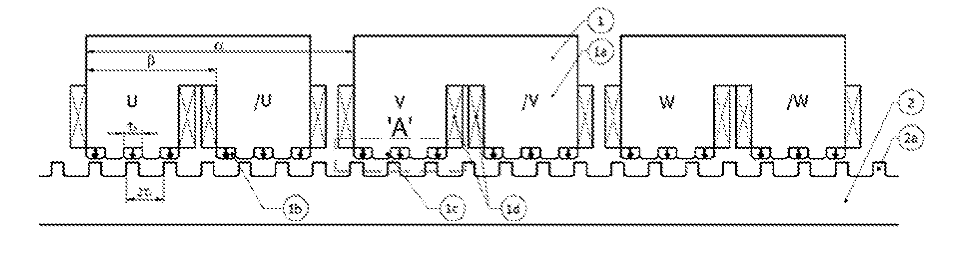
[0053]The electric machines described in the present invention are energy conversion devices which convert electric energy into kinetic energy or convert kinetic energy into electric energy, for example, including a motor, an actuator and a generator. In addition, the electric machines mean devices which implement the above-mentioned energy conversion using linear motion, rotation or a combination of linear motion and rotation.

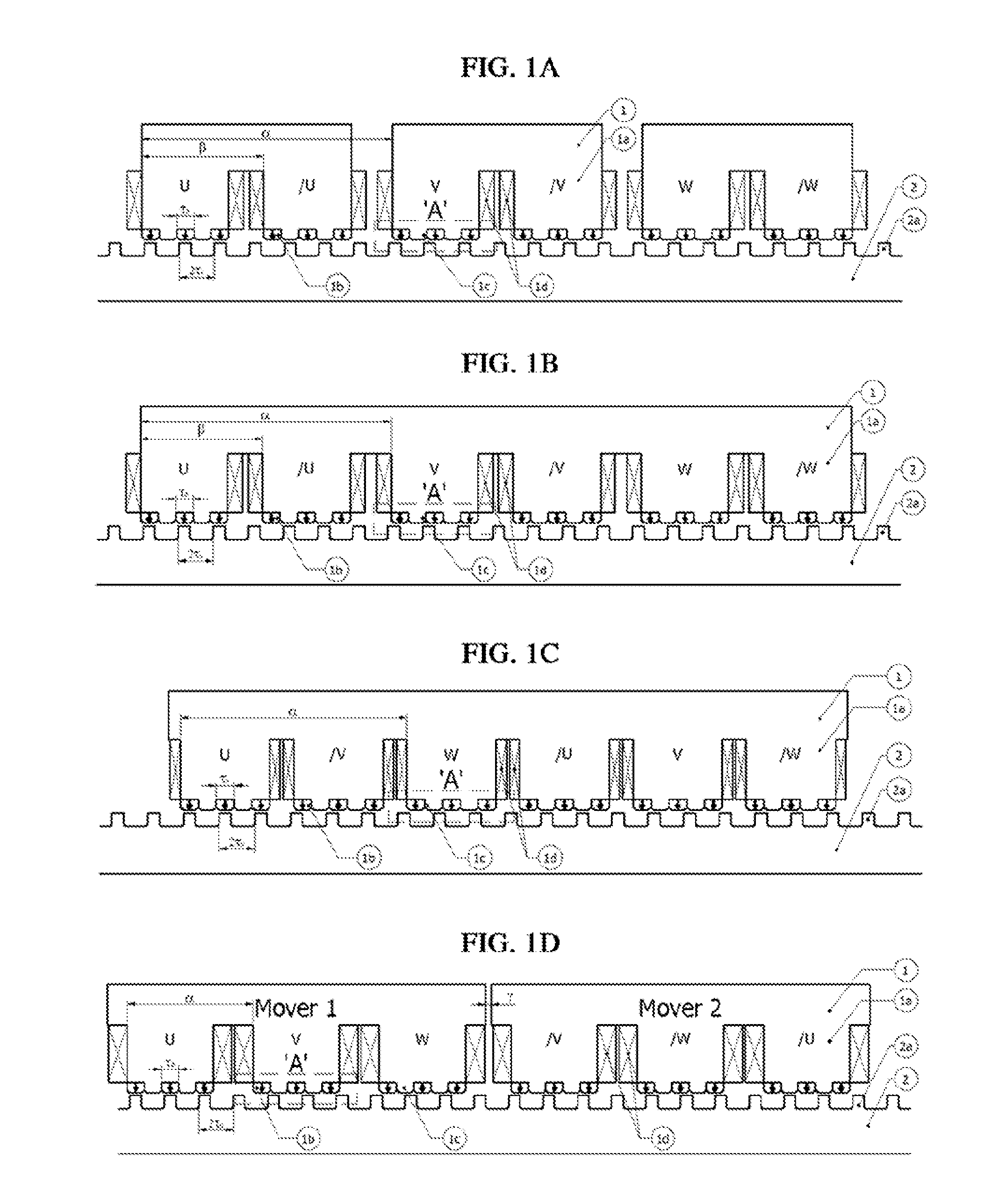
[0054]FIGS. 1A through 1D are views illustrating examples of the construction of a linear electric machine ...


PUM


Abstract

Disclosed herein is a structure for linear and rotary electric machines. The present invention provides a modular mover structure which includes coils that have an electrical phase difference of 180°, so that the path of magnetic flux is shortened, thus reducing the size of the machine and mitigating the back-EMF unbalance. Furthermore, the modular mover structure can be modified into various shapes. For example, when a skew structure is applied to a mover or stator iron core, the force ripples in an electric machine can be reduced. In addition, when a hinge structure is applied to a modular mover iron core, the mover can move in a linear and curved manner. Moreover, the structure of the present invention can be applied to a rotary electric machine. In this case, because the number of poles can be easily increased, a low speed high torque direct drive type rotary electric machine can be realized.

Description

BACKGROUND OF THE INVENTION[0001]1. Field of the Invention[0002]The present invention generally relates to structures for linear and rotary electric machines and, more particularly, to an electric machine which has a modular mover iron core structure such that the path of magnetic flux thereof is shortened, thus reducing the size of the machine and mitigating the unbalance of load back electromotive force (back-EMF), compared to a conventional flux reversal electric machine. Furthermore, the present invention provides various modifications of the proposed embodiment of the electric machine. An example of this would be a linear electric machine in which a hinge structure is applied to a modular mover iron core so that the mover can move in a linearly or curved fashion, or a rotary electric machine that is derived from the proposed linear electric machine.[0003]2. Description of the Related Art[0004]Generally, linear electric machines have been widely used for precision position contr...

Claims


Application Information

Patent Timeline
IPC IPC(8): H02K41/03H02K37/02
CPCH02K16/00H02K21/22H02K21/24H02K2213/03H02K29/08H02K41/033H02K21/26H02K1/12H02K33/02H02K41/02
Inventor CHUNG, SHI UKKANG, DO HYUNWOO, BYUNG CHULKIM, JI WONLEE, JI YOUNGMOON, SEUNG RYUL
Owner KOREA ELECTROTECH RES INST
Why Eureka
Try Eureka