Device for driving a load

a technology for driving a load and a load, applied in the direction of electric variable regulation, process and machine control, instruments, etc., can solve the problems of relative complexity and inefficient construction, and achieve the effect of simple and relatively efficient method and simple and relatively efficient devi

Active Publication Date: 2010-10-14
SIGNIFY HLDG BV
View PDF11 Cites 4 Cited by
  • Summary
  • Abstract
  • Description
  • Claims
  • Application Information

AI Technical Summary

Benefits of technology

[0003]Objects of the invention are to provide a relatively simple and relatively e

Problems solved by technology

This is a relatively complex and r

Method used


Image

  • Device for driving a load
  • Device for driving a load
  • Device for driving a load

Examples


first embodiment

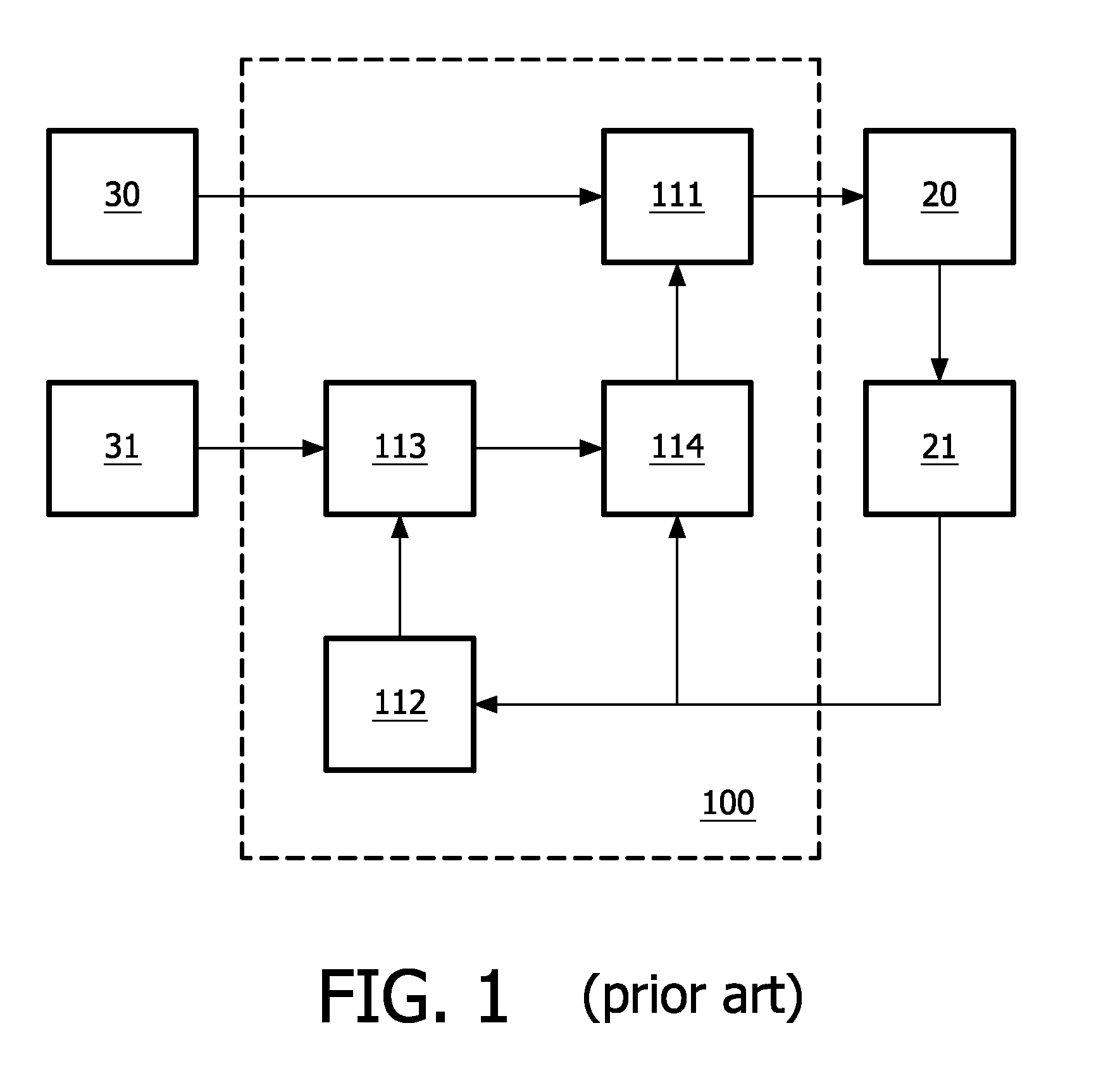
[0046]In the FIG. 2, a device 10 according to the invention is shown. This device 10 comprises a driver 11 coupled to a supplying circuit 30 and to a load 20. The driver 11 is further coupled to a digital controller 13 for controlling the driver 11 in response to a digital parameter signal. The digital controller 13 is coupled to a user interface 31 for receiving a user signal and to a converter 12 for converting an analog parameter signal originating from a sensor 21 coupled to the load 20 and defining a parameter of the load 20 into the digital parameter signal. This digital parameter signal has, during each time interval of a group of two or more time intervals, one out of two possible values. Alternatively, the user interface 31 may be left out, and the sensor 21 may be left out, in which case the analog parameter signal is to be derived from the load 20 or from a point near the load 20. Optionally, the digital controller 13 may be arranged to further control the driver 11 in re...

second embodiment

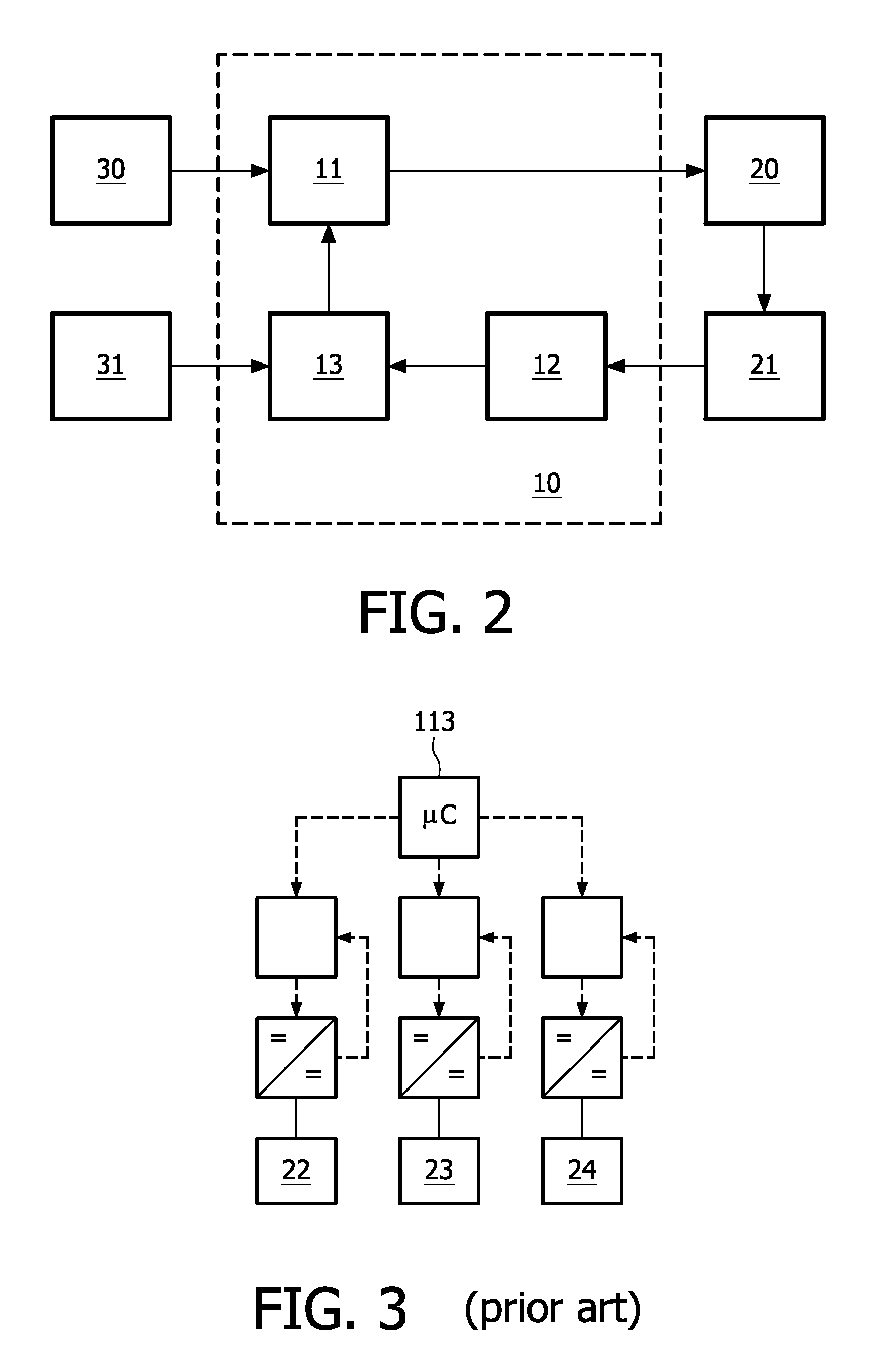
[0048]In the FIG. 4, a device according to the invention is shown. This device comprises a digital controller 13 coupled via respective dc / dc drivers to respective loads 22-24 such as red, green and blue light emitting diodes. In this case, the analog parameter signals are either converted inside the dc / dc drivers or inside the digital controller 13 into the digital parameter signals each having, during each time interval of a group of two or more time intervals, one out of two possible values.

third embodiment

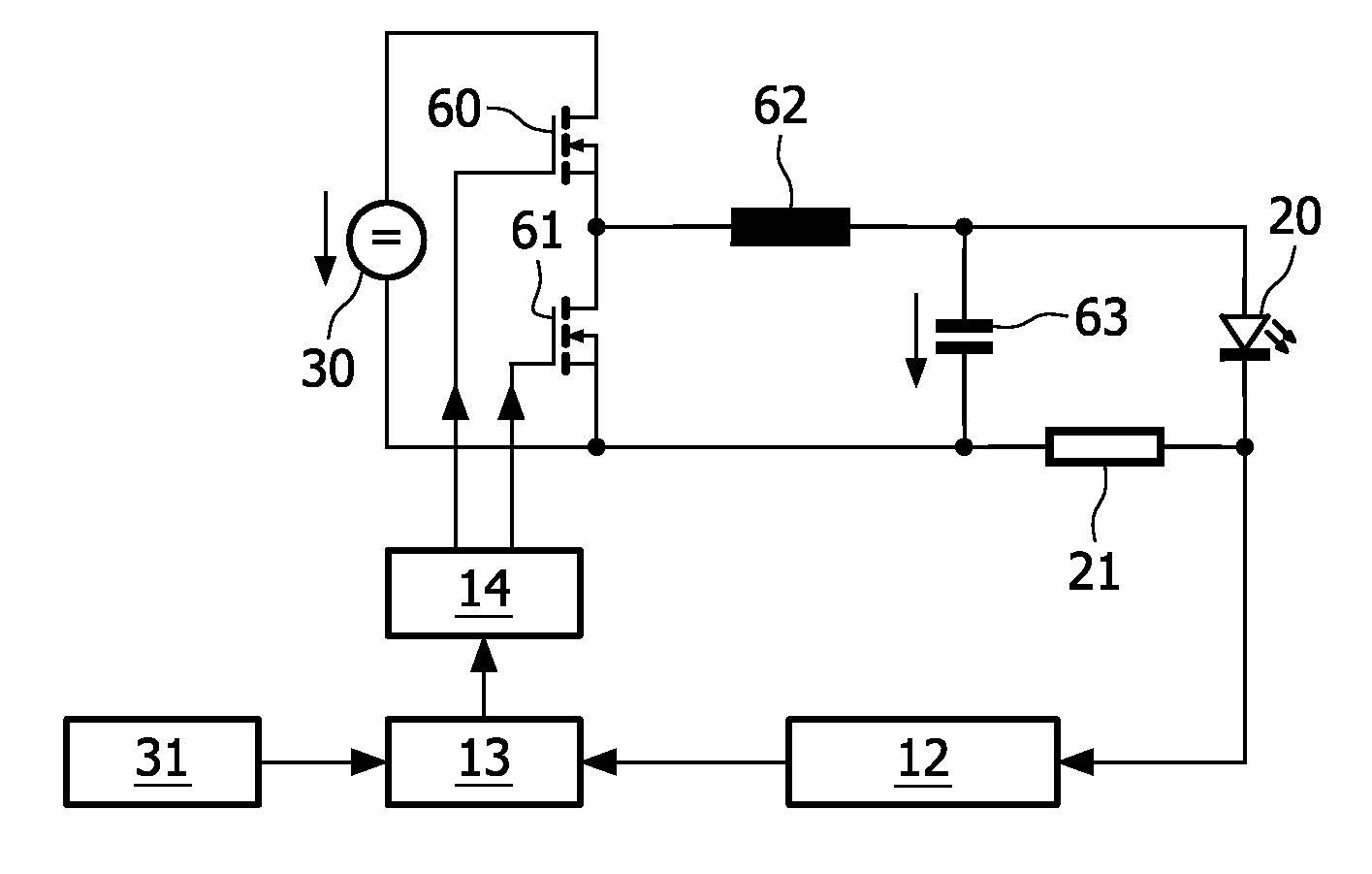
[0049]In the FIG. 5, a device according to the invention is shown. This device comprises a circuit 40-41 for comparing the analog parameter signal with a reference signal and for generating, during each time interval of a group of two or more time intervals, the digital parameter signal having a respective first or second value of the two possible values in case of a respective first or second comparison result. Thereto, the circuit 40-41 comprises a comparator circuit 40 and a timer circuit 41 such as a flip flop. The flip flop is coupled to a clock signal generator 42 for sampling the comparison result from the comparator circuit 40. Other kinds of circuits 40-41 are not to be excluded. The circuit 40-41 controls a switch 50, possibly via further circuitry not shown. This switch 50 such as a transistor opens or closes a serial circuit of a supplying circuit 30 and a diode 51. In parallel to the diode 51, a serial circuit of an inductor 52 and a load 20 and a sensor 21 is present. ...


PUM


Abstract

Devices (10) for driving loads (20) such as organic/inorganic light emitting diodes are provided with drivers (11) for driving the loads (20), with converters (12) for converting first parameter signals defining parameters of the loads (20) into second parameter signals each being defined by one bit per time interval, and with digital controllers (13) for controlling the drivers (11) in response to the second parameter signals. The converter (12) may comprise a comparator circuit (40) and a timer circuit (41) for comparing the first parameter signal with a reference signal and for generating the second parameter signal having a respective first or second value of two possible values in case of a respective first or second comparison result. The parameter may be a current flowing through or light emitted by at least a part of the load (20). The driver (11) may be a buck/boost/buck boost/fly back converter.

Description

FIELD OF THE INVENTION[0001]The invention relates to a device for driving a load, and also relates to a method for driving a load. Examples of such a device are power supply circuits and consumer products and non-consumer products, or parts thereof. Examples of such a load are inorganic and organic light emitting diodes.BACKGROUND OF THE INVENTION[0002]U.S. Pat. No. 6,747,420 B2 discloses in its title a drive circuit for light emitting diodes and discloses in its Figures a driver (circuit 4), a load (LED 1), a digital controller (μC 3) and a converter (R-shunt 6) for converting an analog current signal defining a current flowing through the load into an analog voltage signal. This analog voltage signal is supplied to the driver. The digital controller controls the driver and controls the converter, and the converter instructs the driver. This is a relatively complex and relatively inefficient construction.SUMMARY OF THE INVENTION[0003]Objects of the invention are to provide a relati...

Claims


Application Information

Patent Timeline
IPC IPC(8): H05B33/08H02M1/08H05B44/00
CPCH05B33/0866H05B33/0818H05B45/24H05B45/3725H05B45/375
Inventor JACOBS, JOSEPH HENDRIK ANNA MARIASHEN, JIEHENTE, DIRK
Owner SIGNIFY HLDG BV
Why Eureka
Try Eureka