

Electric power converter
a technology of electric power converter and capacitor, which is applied in the direction of electrical equipment, electrical apparatus, electrical apparatus contruction details, etc., can solve the problems of high capacitor temperature, large heat generation of semiconductor modules, and capacitor deterioration, so as to reduce capacitor temperature rise
- Summary
- Abstract
- Description
- Claims
- Application Information
AI Technical Summary
Benefits of technology
Problems solved by technology
Method used
Image

Examples
first embodiment
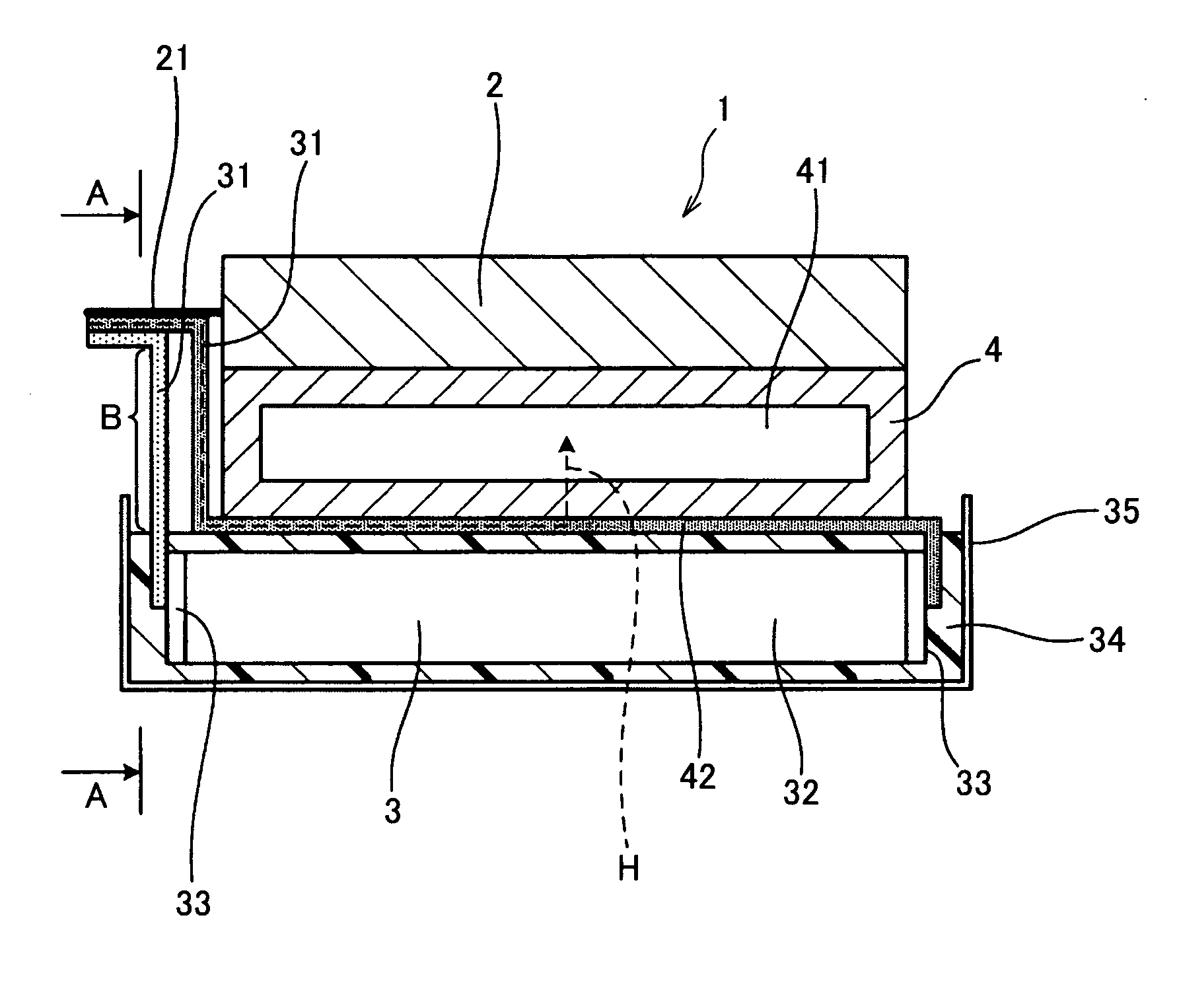
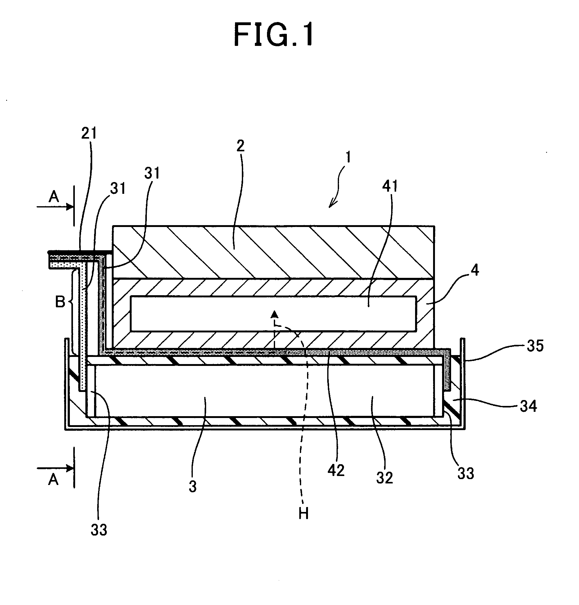
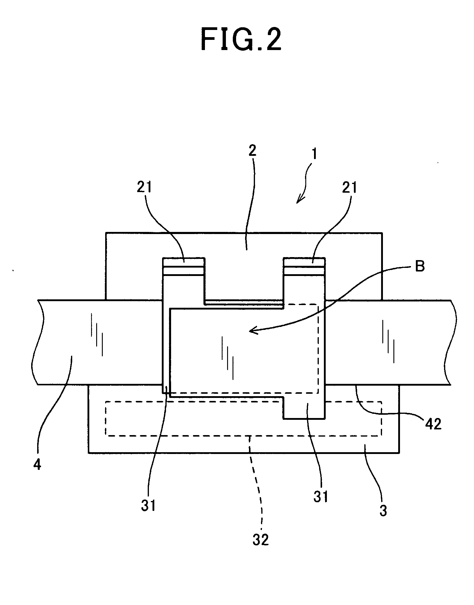
[0060]An electric power converter according to an embodiment of the present invention is explained using FIGS. 1-3.
[0061]As shown in FIGS. 1 and 2, the electric power converter 1 of this embodiment has an electronic component, a semiconductor module 2 in this embodiment, a capacitor 3, and a cooler 4. The semiconductor module has a semiconductor element integrally as well as at least a pair of semiconductor terminals 21. The capacitor 3 is electrically connected to the semiconductor module 2, while at least one of a plurality of capacitor terminals 31 provided in the capacitor 3 is contacted thermally to the cooler 4.
[0062]As shown in FIG. 1, the capacitor terminals 31, which contact the cooler 4 thermally, are arranged between the cooler 4 and the capacitor 3. The cooler 4 also contacts the semiconductor module 2 thermally. The capacitor terminals 31 contacting the cooler 4 thermally are the terminal connected to the semiconductor terminals 21.
[0063]The capacitor 3 has the capacito...
second embodiment
[0098]This embodiment is an example of the electric power converter 1 with which the both sides of the pair of the capacitor terminals 31 contact the cooler 4 thermally, as shown in FIG. 4.
[0099]In the present embodiment, one of the capacitor terminals 31 in the portion between the connecting portion of the capacitor element 32 and the connecting portion of the semiconductor terminals 21 of the semiconductor module 2, is arranged, like the first embodiment, between the capacitor 3 and the cooler 4 while one of the capacitor terminals 31 contacts the cooler 4 via the insulation material.
[0100]Further, a branch part 311 is formed from a portion between the connecting portion of the capacitor element 32 and the connecting portion of the semiconductor terminals 21. The other one of the capacitor terminals 31 is arranged between the capacitor 3 and the cooler 4 while the branch part 311 contacts the cooler 4 via the insulation material.
[0101]Other features are the same as those of the fi...
third embodiment
[0108]This embodiment is an example of the electric power converter 1 whose capacitor terminals 31 are contacted to the cooler 4 thermally via the potting agents 34 of the capacitor 3, as shown in FIGS. 5 and 6.
[0109]The potting agents 34 pack parts of the capacitor terminals 31 together with the capacitor element 32, and the parts of the capacitor terminals 31 thermally contact the cooler 4 via the potting agent 34.
[0110]The electric power converter 1 shown in FIG. 5 has only one of the capacitor terminals 31 contacted to the cooler 4 thermally like the first embodiment, while the electric power converter 1 shown in FIG. 6 has both the capacitor terminals 31 contacted to the cooler 4 thermally like the second embodiment.
[0111]Other features are the same as those of the first embodiment.
[0112]In this embodiment, minimizing the size of the electric power converter 1 can be attained easily.
[0113]Further, this embodiment has the same operation and effect as the first embodiment.
PUM
 Abstract
Description
Claims
Application Information