Method for transmitting data in wireless communication system

a wireless communication system and wireless communication technology, applied in data switching networks, instruments, frequency-division multiplexes, etc., can solve the problems of increasing the overhead caused by control information, the mac layer performance may be affected, and the latency and complexity of the transmission process may increase, so as to achieve the effect of increasing the efficiency of data transmission

Inactive Publication Date: 2010-10-14
LG ELECTRONICS INC
View PDF21 Cites 108 Cited by
  • Summary
  • Abstract
  • Description
  • Claims
  • Application Information

AI Technical Summary

Benefits of technology

[0011]Data transfer efficiency can be increased since a suitable-sized transmission time interval (TTI) can be assigned to various types of data in one frame.

Problems solved by technology

Second, a new system has to operate in the same radio frequency (RF) subcarrier and the same bandwidth as those of a legacy system.
For example, if the TTI size is set to be less than a data transfer block, a transfer block segmentation process has to be performed in the MAC layer, which results in an overhead in performance of the MAC layer.
In addition, latency and complexity may increase in a transmission process since the data transfer block is transmitted through a plurality of TTIs.
Accordingly, control information is additionally required for the multiplexed data transfer block, thereby increasing an overhead caused by the control information.
When the TTI size is fixed to one size with respect to various-sized data, a problem may arise in that latency and complexity increase in the transmission process or an overhead caused by the control information increases.
In addition, since the IEEE 802.16m system has to provide more various types of data services while satisfying a backward compatibility with the IEEE 802.16e system, the use of the TTI whose size is fixed to one size cannot satisfy the various types of data services.

Method used


Image

  • Method for transmitting data in wireless communication system
  • Method for transmitting data in wireless communication system
  • Method for transmitting data in wireless communication system

Examples


Embodiment Construction

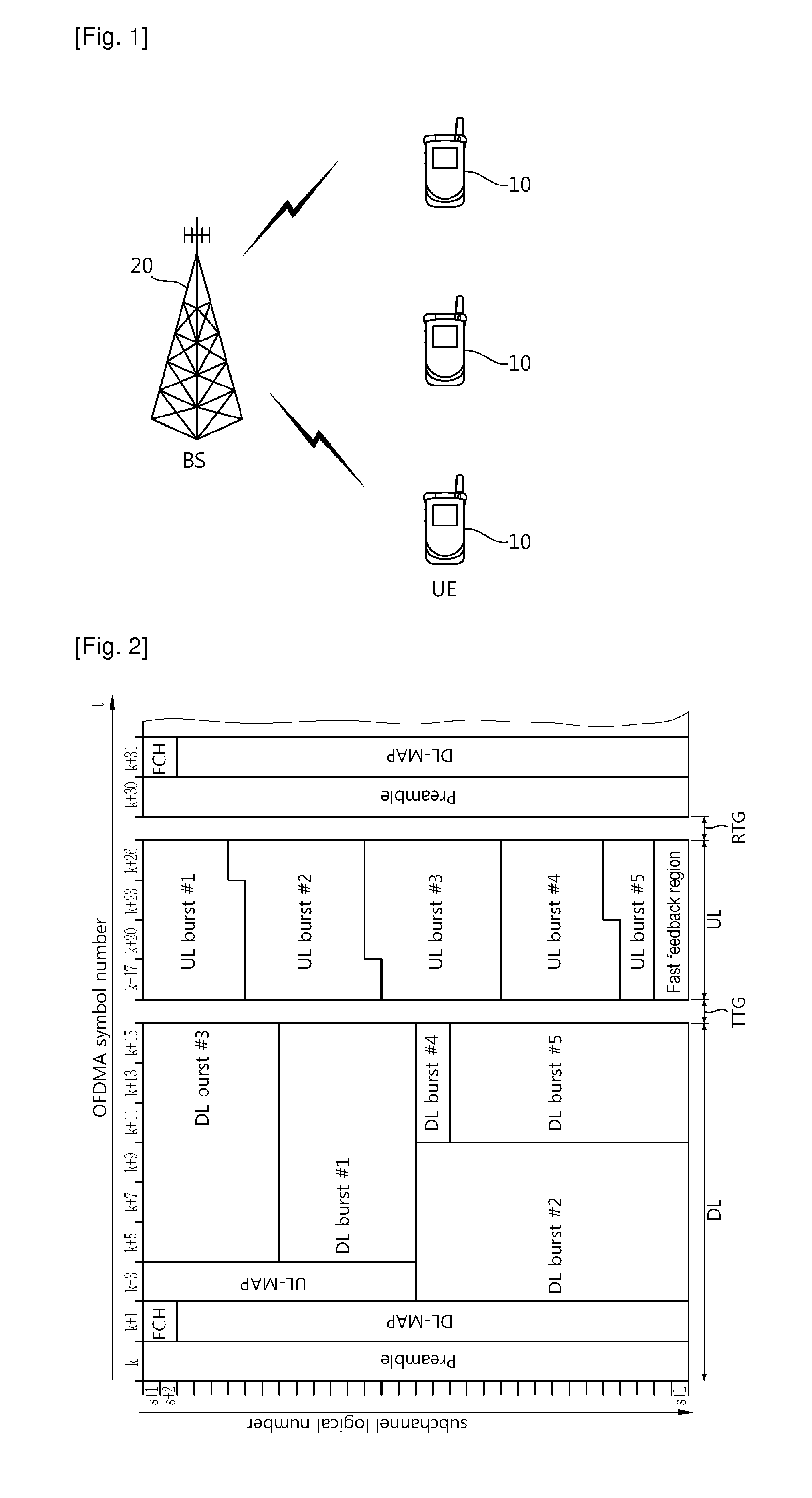
[0021]FIG. 1 shows a wireless communication system. The wireless communication system can be widely deployed to provide a variety of communication services, such as voices, packet data, etc.

[0022]Referring to FIG. 1, the wireless communication system includes at least one user equipment (UE) 10 and a base station (BS) 20. The UE 10 may be fixed or mobile, and may be referred to as another terminology, such as a mobile station (MS), a user terminal (UT), a subscriber station (SS), a wireless device, etc. The BS 20 is generally a fixed station that communicates with the UE 10 and may be referred to as another terminology, such as a node-B, a base transceiver system (BTS), an access point, etc. There are one or more cells within the coverage of the BS 20.

[0023]A downlink represents a communication link from the BS 20 to the UE 10, and an uplink represents a communication link from the UE 10 to the BS 20. In downlink, a transmitter may be a part of the BS 20, and a receiver may be a par...


PUM


Abstract

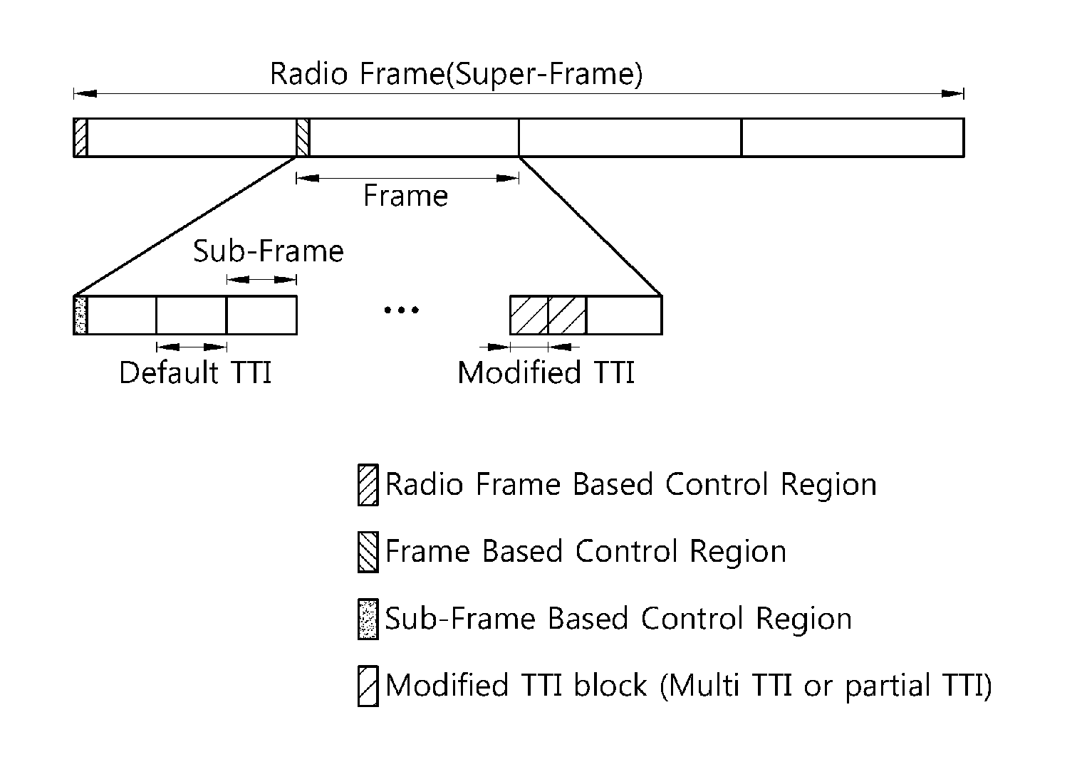
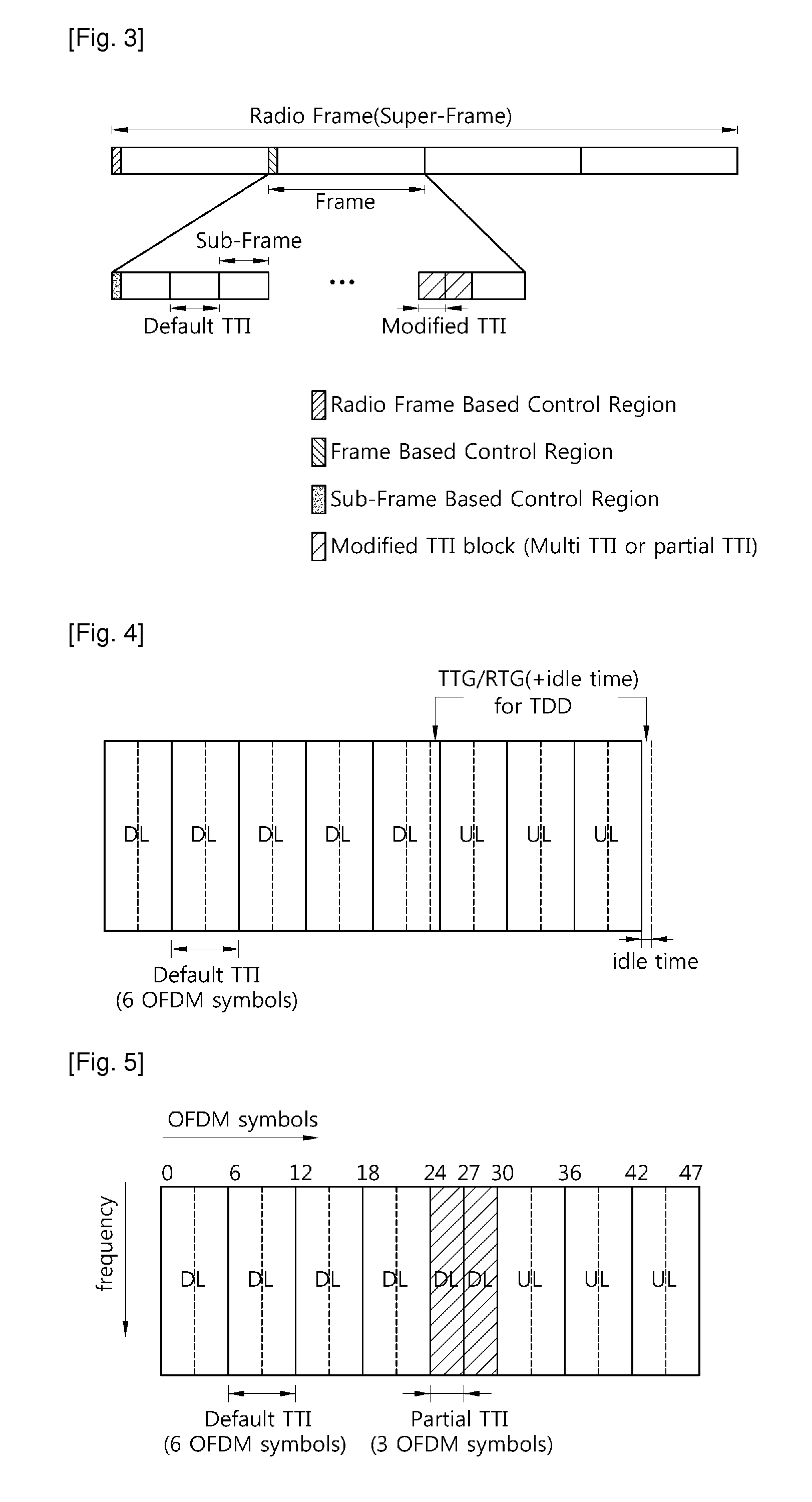
A method for transmitting data in a wireless communication system is provided. The method includes: transmitting first data through a radio resource allocated in a unit of a default transmission time interval (TTI) including at least one sub-frame in a frame including a plurality of sub-frames consisting of a plurality of orthogonal frequency division multiplexing (OFDM) symbols; and transmitting second data through a radio resource allocated in a unit of a modified TTI obtained by changing the number of sub-frames included in the default TTI in the frame.

Description

TECHNICAL FIELD[0001]The present invention relates to wireless communications, and more particularly, to a method for transmitting data by using a frame including a various-sized transmission time interval (TTI) that is a basic unit of scheduling.BACKGROUND ART[0002]The institute of electrical and electronics engineers (IEEE) 802.16 standard provides a technique and protocol for supporting broadband wireless access. The standardization had been conducted since 1999 until the IEEE 802.16-2001 was approved in 2001. The IEEE 802.16-2001 is based on a physical layer of a single carrier (SC) called ‘WirelessMAN-SC’. The IEEE 802.16a standard was approved in 2003. In the IEEE 802.16a standard, ‘WirelessMAN-OFDM’ and ‘WirelessMAN-OFDMA’ are further added to the physical layer in addition to the ‘WirelessMAN-SC’. After completion of the IEEE 802.16a standard, the revised IEEE 802.16-2004 standard was approved in 2004. To correct bugs and errors of the IEEE 802.16-2004 standard, the IEEE 802...

Claims


Application Information

Patent Timeline
Patent Type & Authority Applications(United States)
IPC IPC(8): H04L27/00H04J3/00
CPCH04L5/0007H04L27/2602H04L5/0048H04L5/003H04L27/2603
Inventor MOON, SEONG HONAM, KI HOHAN, SEUNG HEENOH, MIN SEOKKWAK, JIN SAMLEE, HYUN WOOKIM, DONG CHEOLCHO, SUNG GUKWON, YEONG HYEON
Owner LG ELECTRONICS INC
Why Eureka
Try Eureka