System for purifying air through germicidal irradiation and method of manufacture

a technology of purifying air and germicidal irradiation, which is applied in the field of system for purifying air through germicidal irradiation and method of manufacture, can solve the problems of reducing particle size, odor, and odor, and various high temperature coating application techniques have been technically successful, and achieve the effect of enhancing air-surface contact and maximizing photocatalytic surface conta

Active Publication Date: 2010-10-14
HAMPSHIRE DEV LTD
View PDF2 Cites 62 Cited by
  • Summary
  • Abstract
  • Description
  • Claims
  • Application Information

AI Technical Summary

Benefits of technology

[0059]In another embodiment, an effective area of the photocatalytic elements, the UV light source and the arrangement of the elements to form the core cavity can be matched with the apparatus flow rate using methods set forth herein. The photocatalytic planar elements and light source are selected to provide the desired ultraviolet germicidal irradiation dosages (residence time inside the core cavity) at the prescribed air flow rates while maximizing the photocatalytic surface contact between the flowing air and the interiorly illuminated photocatalytically active medium. Turbulent flow also enhances air-surface contact.

Problems solved by technology

Early work with photocatalyst powder coatings encountered particle size minimization and bond-to-substrate issues.
Various high temperature coating application techniques have been technically successful but are economically and practically prohibitive for coating fiber wool, mat, or felt.
Organic binders for powders, such as methylmethacrylate and various organic resins, have been found to emit unacceptable odors under UV-C irradiation.
Unfortunately, the patent discloses no details of the photocatalytic gas purifier, light source, or photocatalyst.
Design-induced turbulence is claimed to increase the dwell time of contaminants in the illumination section.
Convection alone is a slow process that generates a small number of air exchanges per hour in even modest-sized indoor environments.
Light introduced at the ends of the fibers travels along the photocatalyst fibers while partially leaking therefrom and thus causing photocatalytic reactions.
Such light losses (leakage) distribute the light throughout the composite material.
Nevertheless, turbulence does improve the possibility of surface contact.
Convection alone is a slow process that generates a small number of air exchanges per hour in even modest sized indoor environments.
As noted above, organic binders for photocatalytic support structures are unsuitable as they emit unacceptable odors under UV-C irradiation.
Further, Applicant has noted a heightened manufacturing cost associated with cylindrical support structures.

Method used


Image

  • System for purifying air through germicidal irradiation and method of manufacture
  • System for purifying air through germicidal irradiation and method of manufacture
  • System for purifying air through germicidal irradiation and method of manufacture

Examples


Embodiment Construction

General Arrangement

Cylindrical Photocatalytic Element

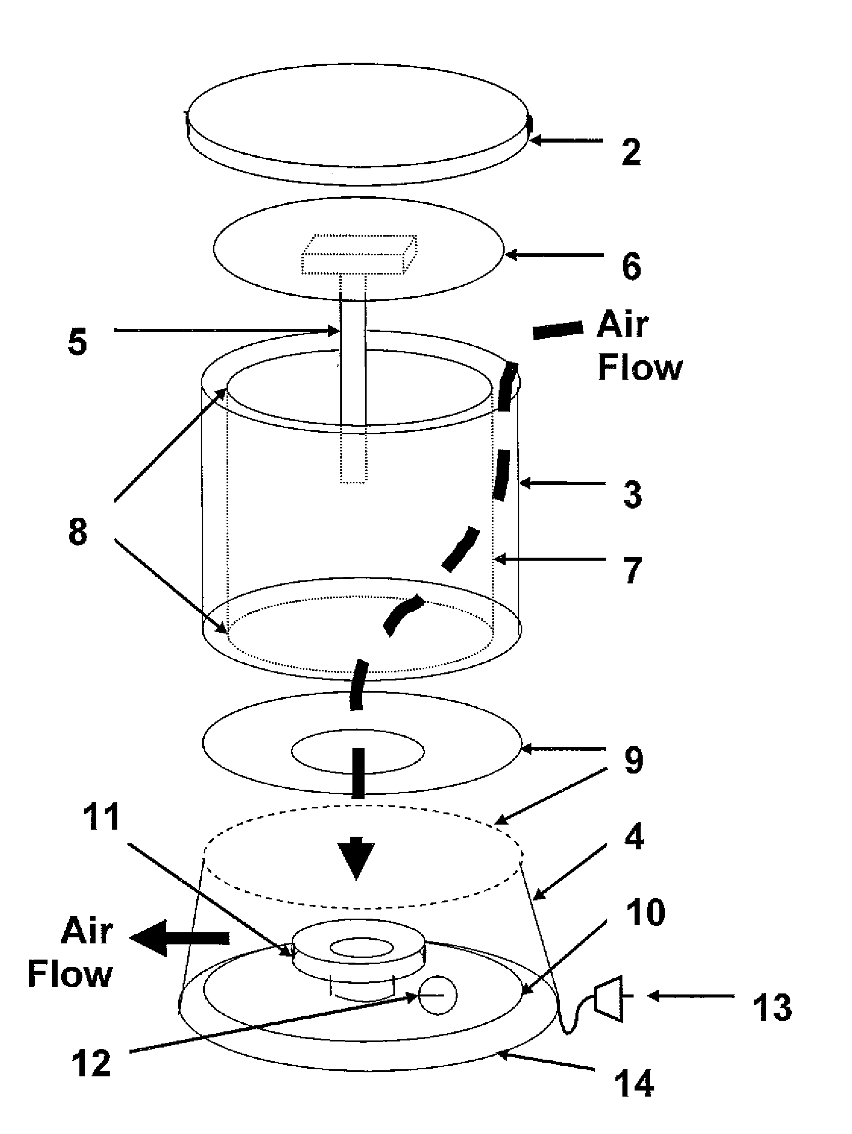
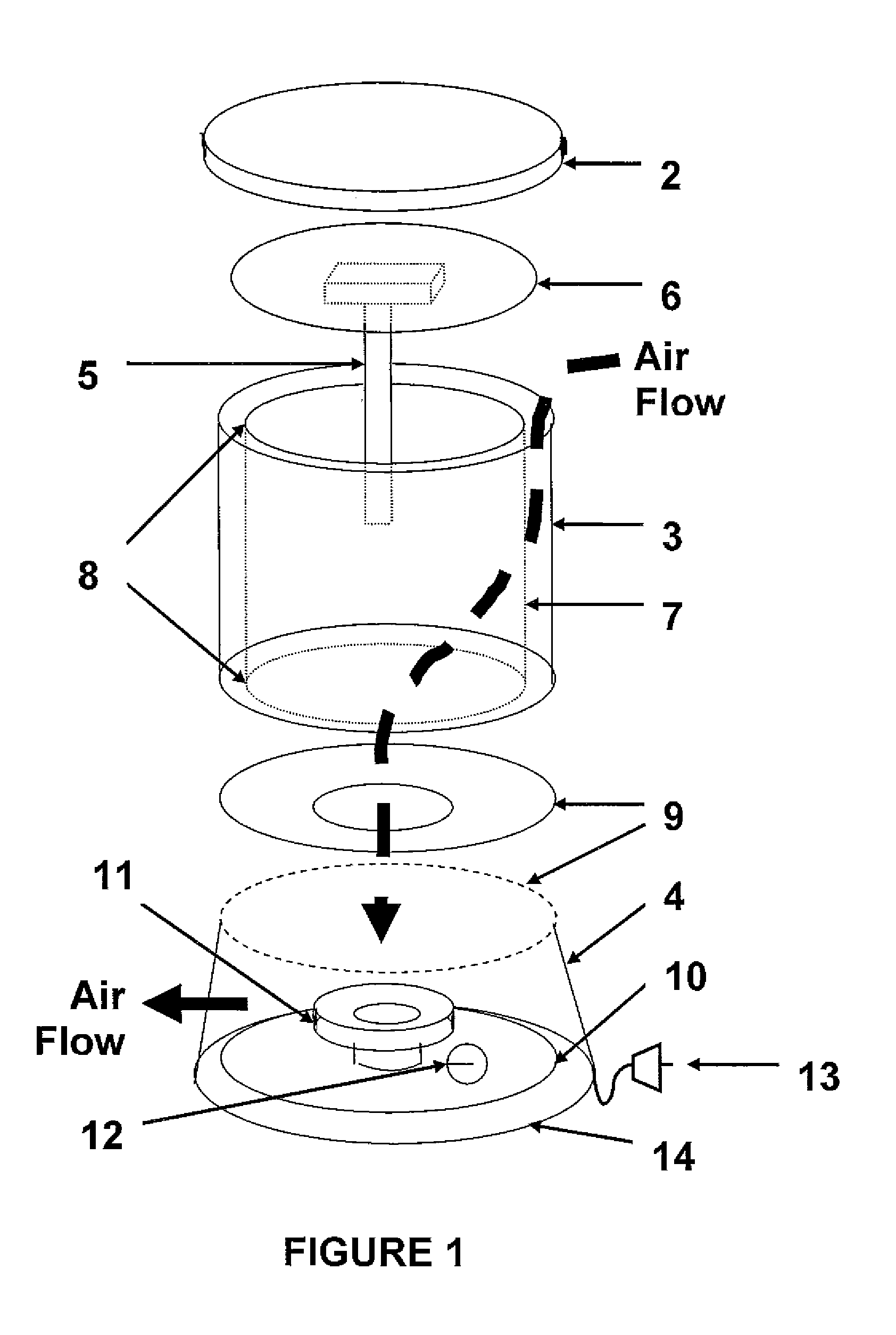
[0087]FIG. 1 is an illustrative schematic diagram of one embodiment of an air purifier system and unit according to the present invention. The system 1 generally includes the housing (top 2, sides 3, and base 4 with air exit ports or louvers), a photocatalyst-activating light source 5 and light source mounting plate 6, photocatalytic cartridge 7 with elastomeric gasket rings 8, photocatalytic cartridge end-seal plate 9 (with central port), electrical component mounting plate 10, fan and motor 11, speed control / switch 12, power cord 13, and base plate 14. When assembled, the mounting plate 6 and cartridge end-seal plate 9 form air-tight seals with the elastomeric gasket rings 8, shown as part of the photocatalytic cartridge 7.

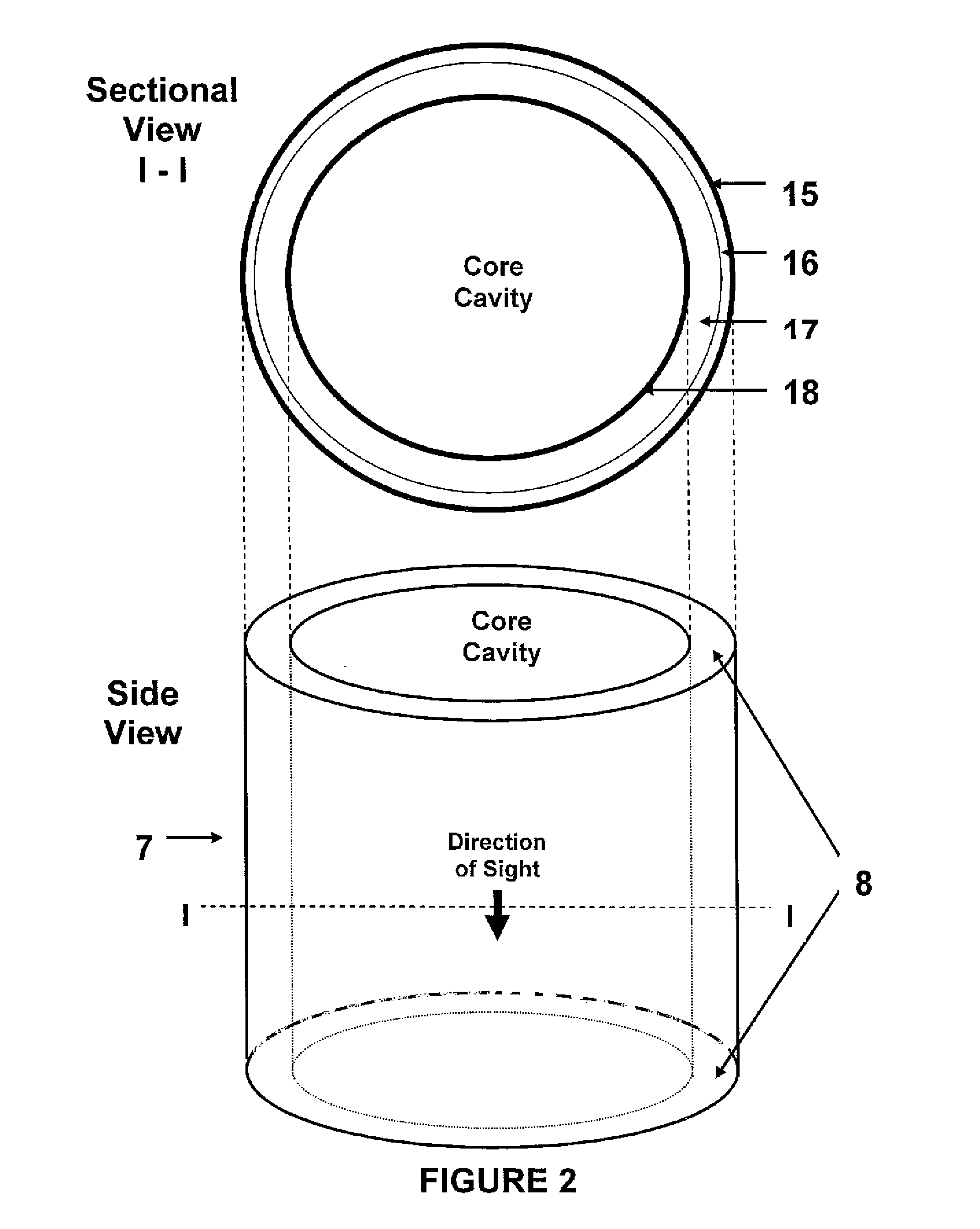
[0088]FIG. 2 is a schematic diagram of components making up a preferred embodiment of the photocatalytic cartridge of claim 1. All elements are sealed inside the end enclosures (elastomeric rings 8, in a prefe...


PUM

PropertyMeasurementUnit
temperatureaaaaaaaaaa
diameteraaaaaaaaaa

Abstract

An air purifying system includes one or more air permeable photocatalytic elements defining a core cavity having a sealed top end and an open bottom end. A sealed air flow path ensures that air travels from an outside of the core cavity, through the one or more photocatalytic elements, into the core cavity, to be expelled through the open bottom end. A UV radiation source disposed within the core cavity irradiates air travelling along the sealed flow path and an interior of the one or more photocatalytic elements. Each photocatalytic element is manufactured using a substrate, that is conductive of and transparent to UV radiation, coated with a photocatalyst. A non-photocatalytically active material is initially coated on the substrate and is then converted to a photocatalyst by calcination.

Description

CROSS-REFERENCE TO RELATED APPLICATIONS[0001]This application claims the benefits under 35 U.S.C. 120, of U.S. patent application Ser. No. 11 / 835,899, filed on Aug. 8, 2007, and published as US 2009 / 0041632 on Feb. 12, 2009, which is incorporated fully herein by reference.BACKGROUND OF THE INVENTION[0002]The present invention relates to a system and method of manufacturing the same, for efficiently purifying indoor air by combining forced (variable speed) air movement (fan and motor), filtration, ultraviolet germicidal irradiation, and photocatalysis in an air purifier unit.[0003]Some of the earliest published references to titania (titanium dioxide or TiO2) photocatalysts are by Formenti, M., et al., “Heterogeneous Photocatalysis for Oxidation of Paraffins”, Chemical Technology 1, 680-686, 1971 and U.S. Pat. No. 3,781,194 issued Dec. 25, 1973. Since the 1972 discovery of the photocatalytic splitting of water on titanium dioxide electrodes, by Fujishima and Honda, the science and te...

Claims


Application Information

Patent Timeline
Patent Type & Authority Applications(United States)
IPC IPC(8): A61L9/20B23P17/00
CPCA61L9/205F24F2003/1667B01J35/004B01J21/063B01D53/34Y10T29/49986F24F13/28A61L9/20A61L9/014A61L9/00B01D24/001B01D24/04F24F8/22
Inventor DAY, EDWIN DAVIDDESCHNER, BERNARD K.
Owner HAMPSHIRE DEV LTD
Why Eureka
Try Eureka