Dual-mode electromechanical variable speed transmission apparatus and method of control

a technology of electromechanical variable and transmission apparatus, which is applied in the direction of electric propulsion mounting, transportation and packaging, gearing, etc., can solve the problems of reducing power transmission efficiency and constraining the effective operating speed ratio of transmission, so as to improve the efficiency of power transmission and avoid internal power circulation , the effect of extending the operational speed ratio rang

Inactive Publication Date: 2010-10-14
SHANDONG LIANCHENG GREENMAX TECH
View PDF10 Cites 106 Cited by
  • Summary
  • Abstract
  • Description
  • Claims
  • Application Information

AI Technical Summary

Benefits of technology

[0004]One of the objectives of current invention is to overcome the aforementioned drawbacks of prior art by providing a novel family of dual-mode electro-mechanical variable speed transmissions that share the common design feature and performance characteristics. These transmissions can operate under at least two different power splitting modes, offering higher power transmission efficiency by avoiding internal power circulation. These transmissions are capable of providing, in a wide range, continuously variable output to input speed ratio and independent power regulation. They significantly extend the operational speed ratio range.
[0007]Said dual-mode electro-mechanical variable speed transmission includes at least a counter shaft and at least a clutch installed on the counter shaft. The second electric machine selectively couples to two different branches of the gear system via the counter shaft and the clutch or clutches, to realize two different power splitting modes. To ensure speed synchronization between the components that the clutch is to connect during the shifting between two power split modes, the speed ratios between the second electric machine and the branch it connects and the branch it is about to connect must satisfy a predetermined proportional relationship. Said relationship is determined by the characteristic parameters of the gear system. At the switching point between different power splitting modes, the torque of the second electric machine is essentially zero. No torque impact exerts on the clutch. This leads to a smooth, continuous and non-interruptive operation in terms of speed, torque and power for components associated with the input shaft, the output shaft system and the first and second electric machines.
[0010]Above mentioned technical solution has following benefits: it offers a novel dual-mode electro-mechanical variable speed transmission with reduced power demands on electric machines. Said transmission has simple and compact structure and low manufacturing cost. It is capable of providing continuous operation from reverse to stop and to forward, without requiring the conventional launching device. Said transmission significantly improves the overall efficiency of the vehicle.

Problems solved by technology

One of the power paths sees more power than that transmitted through the transmission, which reduces power transmission efficiency.
This, to a large extent, constrains the effective operating speed ratio of the transmission.

Method used


Image

  • Dual-mode electromechanical variable speed transmission apparatus and method of control
  • Dual-mode electromechanical variable speed transmission apparatus and method of control
  • Dual-mode electromechanical variable speed transmission apparatus and method of control

Examples


embodiment 1

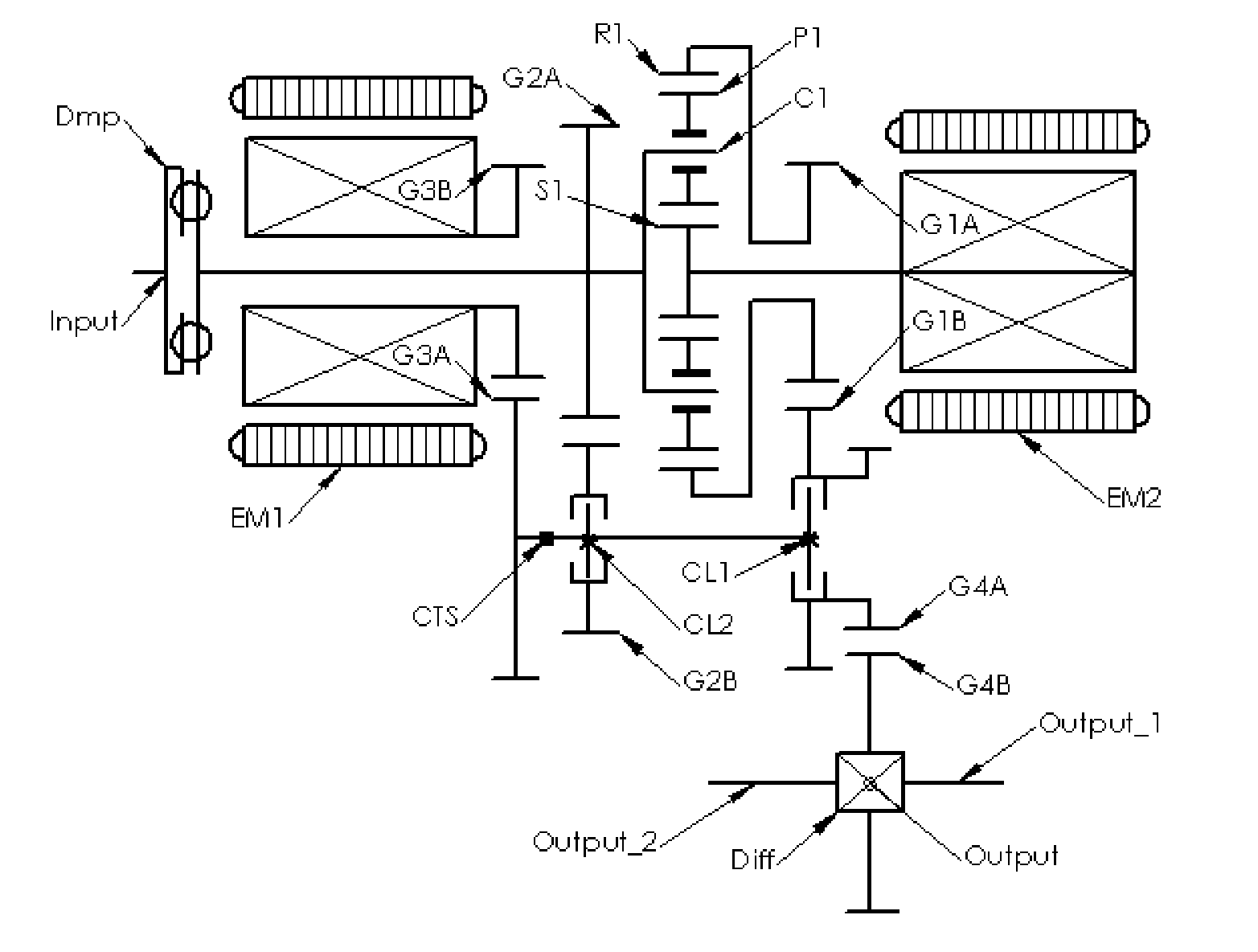
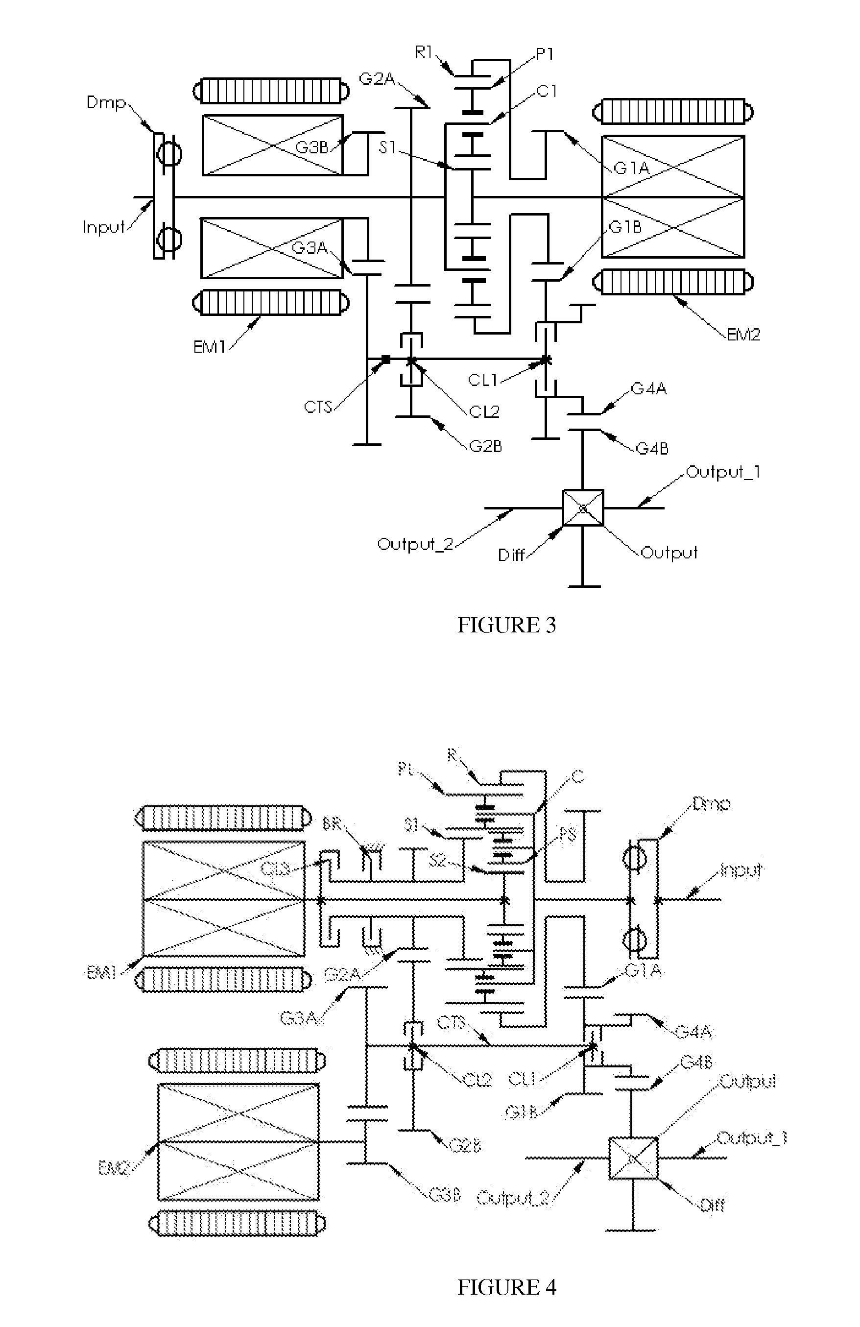
[0025]In embodiment 1, the rotor of the first electric machine EM1 is directly coupled to sun gear S, establishing a connection with the first branch of the three-branch gear system with a fixed speed ratio (1). The input shaft (Input) couples to the planet carrier C via a torsion damper or a shuck load absorber (Dmp), establishing a connection with the second branch of the three-branch gear system with a fixed speed ratio (1). The output shaft system (Output) couples to ring gear R via two pairs of gears G1A, G1B and G4A, G4B, establishing a connection with the third branch of the three-branch gear system with a fixed speed ratio (GR1×GR4). The second electric machine EM2, either couples to the ring gear R with the speed ratio of GR1×GR3, through gears G1A, G1B and gears G3A, G3B, establishing a selective connection with the third branch of the three-branch gear system, or couples to the planet carrier C with speed ratio of GR2×GR3, through gears G2A, G2B and gears G3A, G3B, establ...

embodiment 2

[0041]FIG. 4 shows embodiment 2 of the current invention. It represents a typical example of the second type of embodiments. The transmission shown in FIG. 4 is comprised of a four-branch planetary gear system, an input shaft (Input), a counter shaft (CTS), an output shaft system (Output), a first clutch CL1, a second clutch CL2, and a first and second electric machines EM1, EM2 along with their electric drives (CTRL, not shown). Said four-branch planetary gear system is constituted by a Ravigneaux planetary gear-train. It contains a large sun gear S1, a small sun gear S2, a set of long planet gear PL, a set of short planet gear PS, a ring gear R and a planet carrier C. Each of said long planet gears PL is in internal meshing engagement with the ring gear R and in external meshing engagement with the large sun gear S1; each of said short planet gears PS is in external meshing engagement with a corresponding long planet gear PL and with the small sun gear S2. Said small sun gear S2 c...

embodiment 3

[0078]The rotor of the first electric machine EM1 couples directly to the first ring gear R1, establishing a connection to the first branch of the four-branch gear system with a fixed speed ratio (1). The output shaft system (Output) couples to the second ring gear R2 through gear sets G1A, G1B (G4A), G4B, establishing a connection to the second branch of the four-branch gear system with a fixed speed ratio of GR1×GR4. Input shaft (Input) couples through a torsion damper Dmp to the planet carrier C, establishing a connection to the third branch of the four-branch gear system with a fixed speed ratio (1). The second electric machine EM2 selectively either couples to the second ring gear R2 through gear set G1A, G1B, establishing a connection to the second branch with a first speed ratio of GR1, or couples to the sun gear S through gear set G2A, G2B, establishing a connection to the fourth branch of the four-branch gear system with a second speed ratio GR2. Here GR1, GR2 and GR4 are g...


PUM


Abstract

The current invention discloses a dual-mode electro-mechanical variable speed transmission. Said transmission includes an input shaft, an output shaft system, a planetary gear system having at least three co-axial rotating members, two electric machines along with the associated controllers for the electric machines, and at least a clutch. Said planetary gear system has at least three branches; each branch corresponds to a co-axial rotating member. The first branch couples to the first electric machine with a fixed speed ratio; another branch couples to the input shaft with a fixed speed ratio; and yet anther branch couples to the output shaft system with a fixed speed ratio; the second electric machine couples selectively to two of the branches in the planetary gear system with different speed ratios. Said two branches are not the first branch and one of the said two branches is connected to the output shaft system. Said dual-mode electro-mechanical variable speed transmission is capable of providing at least two power splitting operation modes, including an output power splitting mode. Different operation modes cover different speed ratio regimes. At the mode switching point, the corresponding clutch or clutches is automatically synchronized. Thus the speeds of the rotation members of the transmission are continuous, and the transmission is free from shock loads at the operating mode switching point. In addition, said transmission is capable of providing operations with at least a fixed input-to-output speed ratio.

Description

TECHNICAL FIELD[0001]The invention is related to a dual mode electro-mechanical variable speed transmission. It can be used in a wide variety of vehicle applications and power equipments.TECHNOLOGY BACKGROUND[0002]An internal combustion engine operates in a certain range of speed and power. Inside this range, there usually exists a smaller regime where the engine archives the best performance. On the other hand, however, driving conditions vary enormously, not only in wheel speed but also in driving torque at the drive wheels. A combination of a given speed and torque defines a power state. Matching the power state of the engine with that of the drive wheels is one of the primary functions for a transmission.[0003]In recent years, the development of hybrid technology provides new avenues for achieving improved match in power state between the internal combustion engine and the drive wheels. Among various power-train architecture designs, the most representative is the electro-mechan...

Claims


Application Information

Patent Timeline
Patent Type & Authority Applications(United States)
IPC IPC(8): B60W10/04B60W20/00F16H61/66B62D65/10
CPCB60K1/02Y10T477/26B60K6/445B60K6/547F16H3/728F16H2037/0873F16H2037/101F16H2037/103F16H2037/104F16H2200/0034F16H2200/2005F16H2200/2007F16H2200/2035F16H2200/2097Y02T10/6239B60W10/02B60W10/08B60W10/11Y10T477/23B60K6/365Y02T10/62
Inventor AI, XIAOLINXUE, RUIXUE, ZHONGHEAI, XIAOZHI
Owner SHANDONG LIANCHENG GREENMAX TECH
Why Eureka
Try Eureka