Liquid concentration measuring device

a technology of liquid concentration and measuring device, which is applied in the direction of instruments, material electrochemical variables, electrical control, etc., to achieve the effect of avoiding the abnormal determination of the fuel system

Inactive Publication Date: 2010-10-21
DENSO CORP
View PDF4 Cites 14 Cited by
  • Summary
  • Abstract
  • Description
  • Claims
  • Application Information

AI Technical Summary

Benefits of technology

[0046]Moreover, as in the above-described engine control system, according to a nineteenth example aspect of the present invention, the normal range is set to be wider than in the case of the normality when the failure determining section determines that the failure has occurred. Thus, the abnormality determination of the fuel system can be avoided.

Problems solved by technology

When the stuck failure abnormality occurs, the measurement value becomes a fixed value, However, even when the measurement value becomes the fixed value, whether the measurement value is abnormal or not cannot be determined if the measurement is performed at a single frequency.

Method used


Image

  • Liquid concentration measuring device
  • Liquid concentration measuring device
  • Liquid concentration measuring device

Examples


first embodiment

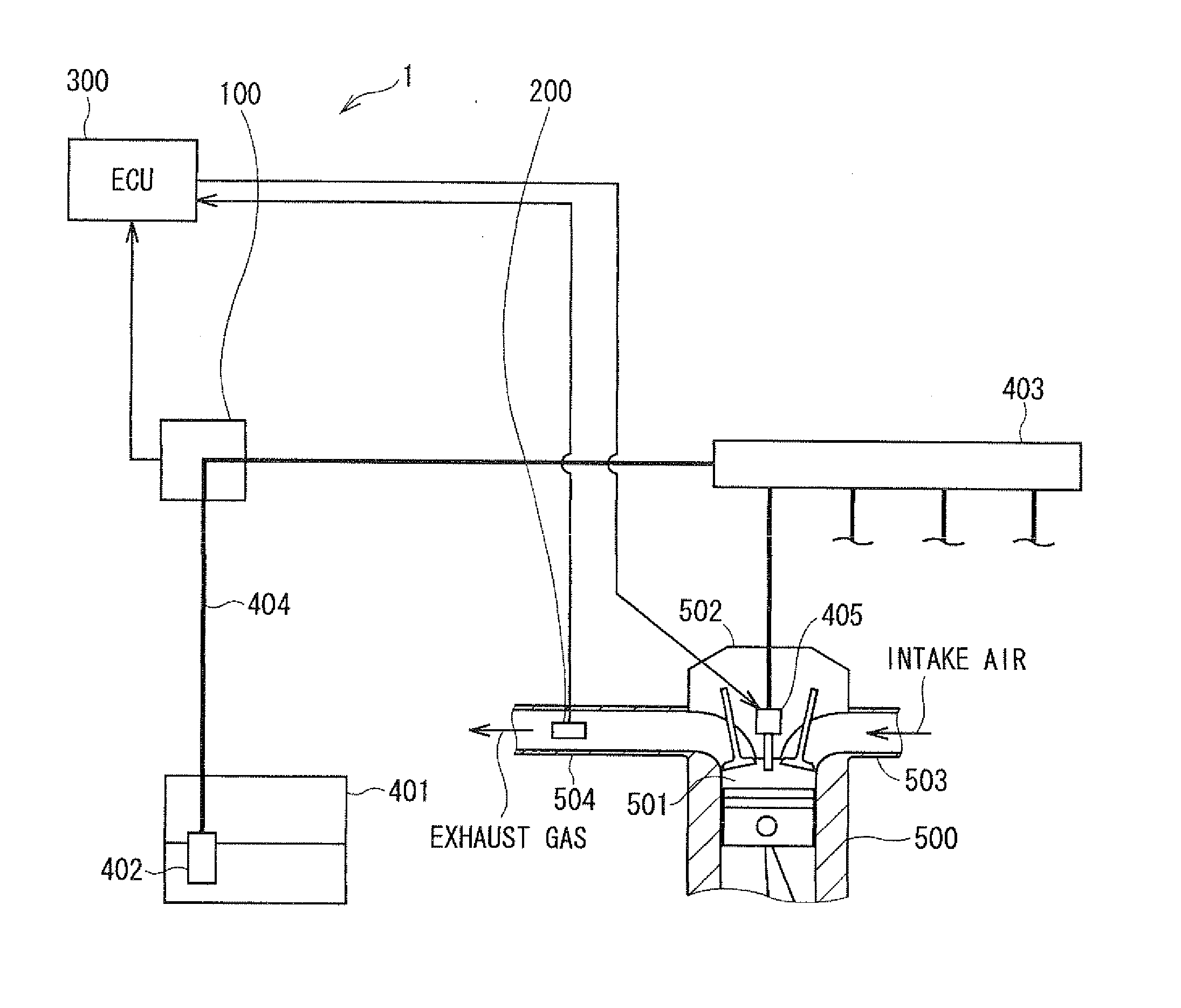
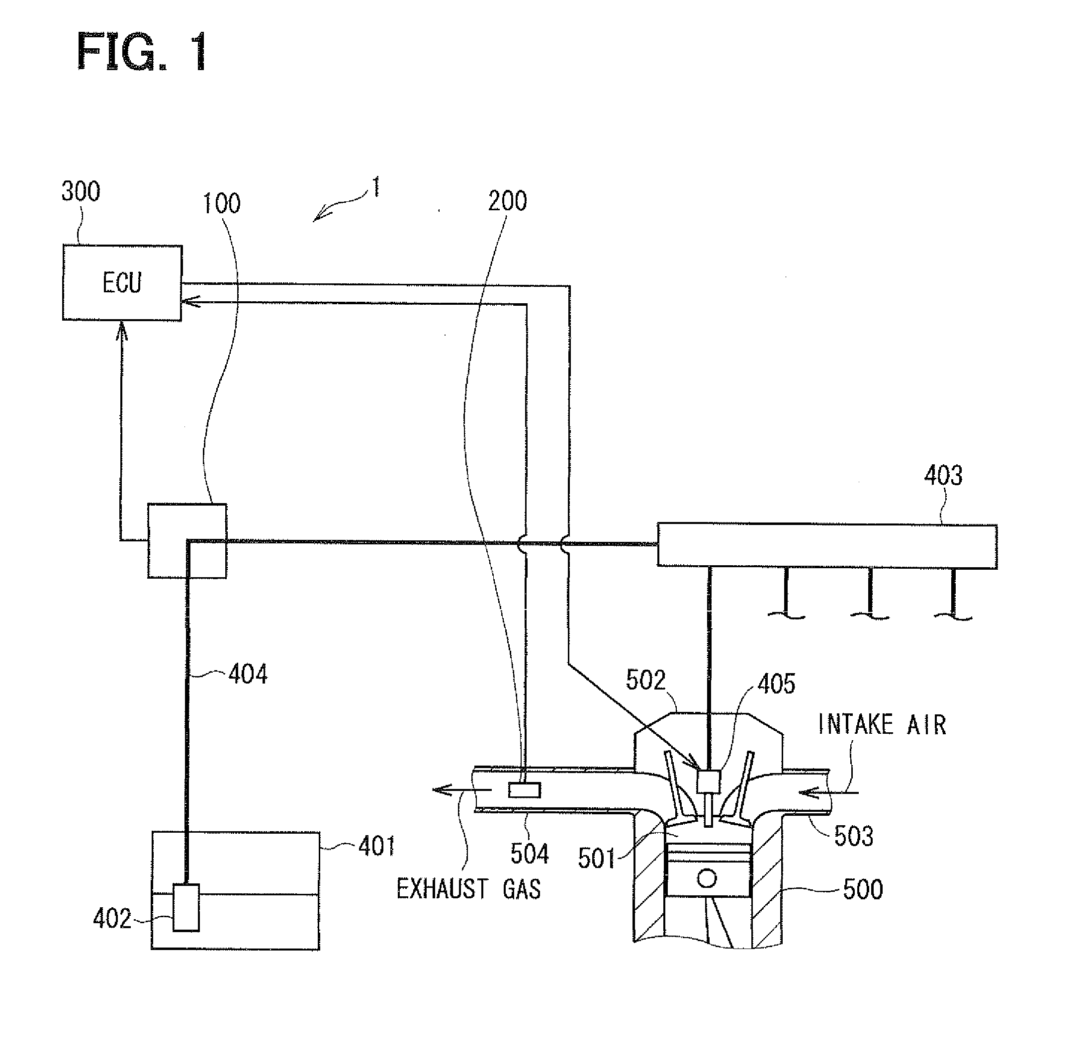
[0069]Hereinafter, the present invention will be described with reference to the drawings. An engine control system according to the present embodiment is mounted and used in a vehicle and performs the optimum fuel injection to a combustion chamber of an engine. As shown in FIG. 1, the engine control system 1 according to the present embodiment has an alcohol concentration sensor 100, an air-fuel ratio sensor 200 and an engine ECU 300 as main components.

[0070]The alcohol concentration sensor 100 measures an ethanol concentration in a mixed gasoline, which is drawn from a fuel tank 401 by a fuel pump 402. Therefore, the alcohol concentration sensor 100 is provided in a middle of a pipe 404 leading from the fuel tank 401 to a fuel rail 403.

[0071]Multiple injectors 405 are connected to the fuel rail 403. The injector 405 injects the fuel to a combustion chamber 501 of a cylinder 500 of the engine. Therefore, the injector 405 is fixed to an engine head 502 to enable the fuel injection t...

second embodiment

[0139]Next, the present invention will be described.

[0140]In the above-described first embodiment, the microcomputer50 of the alcohol concentration sensor 100 determines the failure. Regarding this point, the engine ECU 300 determines the failure in the second embodiment.

[0141]Next, sensor output processing replacing the above-described sensor output processing (refer to FIG. 6) will be explained with reference to FIG. 16, first. Then, failure determination processing performed in the engine ECU 300 will be explained with reference to FIG. 19. The other general configuration and the like are the same as the above-described first embodiment.

[0142]In first 5400 of FIG. 16, the measurement value S(f1) is read. This processing is the same as S100 in FIG. 6. The measurement value S(f2) is read in following S410. This processing is the same as S110 in FIG. 6. Timings for reading the measurement values S(f1), S(f2) are the same as those explained in the above first embodiment.

[0143]In foll...


PUM


Abstract

A microcomputer of an alcohol concentration sensor reads a first measurement value corresponding to a first frequency and reads a second measurement value corresponding to a second frequency. The microcomputer calculates a difference between the first and second measurement values. The microcomputer performs stuck failure abnormality determination when a state where the difference between the measurement values is equal to or smaller than a predetermined value continues. The microcomputer outputs a PWM signal of a specific frequency, which is different from a frequency in a case of a normality, to an engine ECU. Thus, a failure of the alcohol concentration sensor can be surely determined.

Description

CROSS REFERENCE TO RELATED APPLICATION[0001]This application is based on and incorporates herein by reference Japanese Patent Application No. 2009-103104 filed on Apr. 21, 2009.BACKGROUND OF THE INVENTION[0002]1. FIELD OF THE INVENTION:[0003]The present invention relates to a liquid concentration measuring device that measures an alcohol concentration and the like.[0004]2. DESCRIPTION OF RELATED ART:[0005]Recently, low-pollution alcohol blended gasoline has been attracting attention as fuel for an automobile. Such the mixed gasoline has the optimum air-fuel ratio different from that of fuel consisting of only gasoline. Therefore, it is important to measure a content of the alcohol in the mixed gasoline, i.e., an alcohol concentration, in order to perform fuel injection control to achieve the optimum air-fuel ratio for the mixed gasoline.[0006]Conventionally, there has been proposed a control device of an engine that measures an alcohol concentration and that controls a fuel injectio...

Claims


Application Information

Patent Timeline
Patent Type & Authority Applications(United States)
IPC IPC(8): F02D41/00G01R27/26
CPCF02D19/0602F02D19/0634Y02T10/36F02D41/0025F02D19/0655Y02T10/30
Inventor UCHIDA, AKIKAZUTARUI, JUNANNOURA, TOSHIKIKATSURAHARA, HIROSHI
Owner DENSO CORP
Why Eureka
Try Eureka