Pump Iron Restraint System

a technology of iron restraints and pins, which is applied in the direction of machine supports, household objects, applications, etc., can solve the problems that the components need not be specifically designed, and achieve the effect of achieving wireline tension, easy and quick assembly, and convenient assembly

Inactive Publication Date: 2010-10-21
PENNY TECH S A R L
View PDF9 Cites 10 Cited by
  • Summary
  • Abstract
  • Description
  • Claims
  • Application Information

AI Technical Summary

Benefits of technology

[0003]In accordance with the present disclosure, a pump iron restraint system is disclosed in which a fastening system is coupled to successive joints of pump iron and a wireline is threaded through the fastening system and connected to suitable anchorages at each end. The fastening system for each joint of pump iron may comprise a pair endless flat straps, each of which is coupled by a choker hitch to one of the joints of pump iron One end of each of the endless flat straps is inserted into a shackle. A wireline is placed through the space formed by the pin and the shackle and a screw pin is inserted to close the eye of the shackle to prevent the endless flat straps from being removed. The wireline is secured to fixed objects at the well site so that the wireline is taut. A snatch block that is coupled to a shackle may also be used to achieve tension in the wireline. The use of the pump iron restraint system restrains the pump iron in the event of a failure of the pump iron system, thereby providing a safe area for employees to work. If a joint of pump iron fails, the pump iron restraint system holds the failed joint in place and prevents the force of the expelled gas and / or fluid from causing the remainder of the line to flail and injure persons or property.
[0004]One technical advantage of the present disclosure is the provision of a pump iron restraint system that can be easily and quickly assembled with parts that are commonly found in rigging shops that provide services to the well servicing and drilling industry. The pump iron restraint system can be readily assembled from components that are typically found in a well servicing and drilling environment. As a result, components need not be specifically designed for use in the pump iron restraint system. Another technical advantage of the present disclosure is that the disclosed system is unobtrusive and does not add significant additional complexity to the existing pump iron system. Another technical advantage is that the pump iron restrain system has a small footprint and introduces relatively little in the way of additional parts into the surface area of the well site. Other technical advantages will be apparent to those of ordinary skill in the art in view of the following specification, claims, and drawings.

Problems solved by technology

As a result, components need not be specifically designed for use in the pump iron restraint system.

Method used


Image

  • Pump Iron Restraint System
  • Pump Iron Restraint System
  • Pump Iron Restraint System

Examples


Embodiment Construction

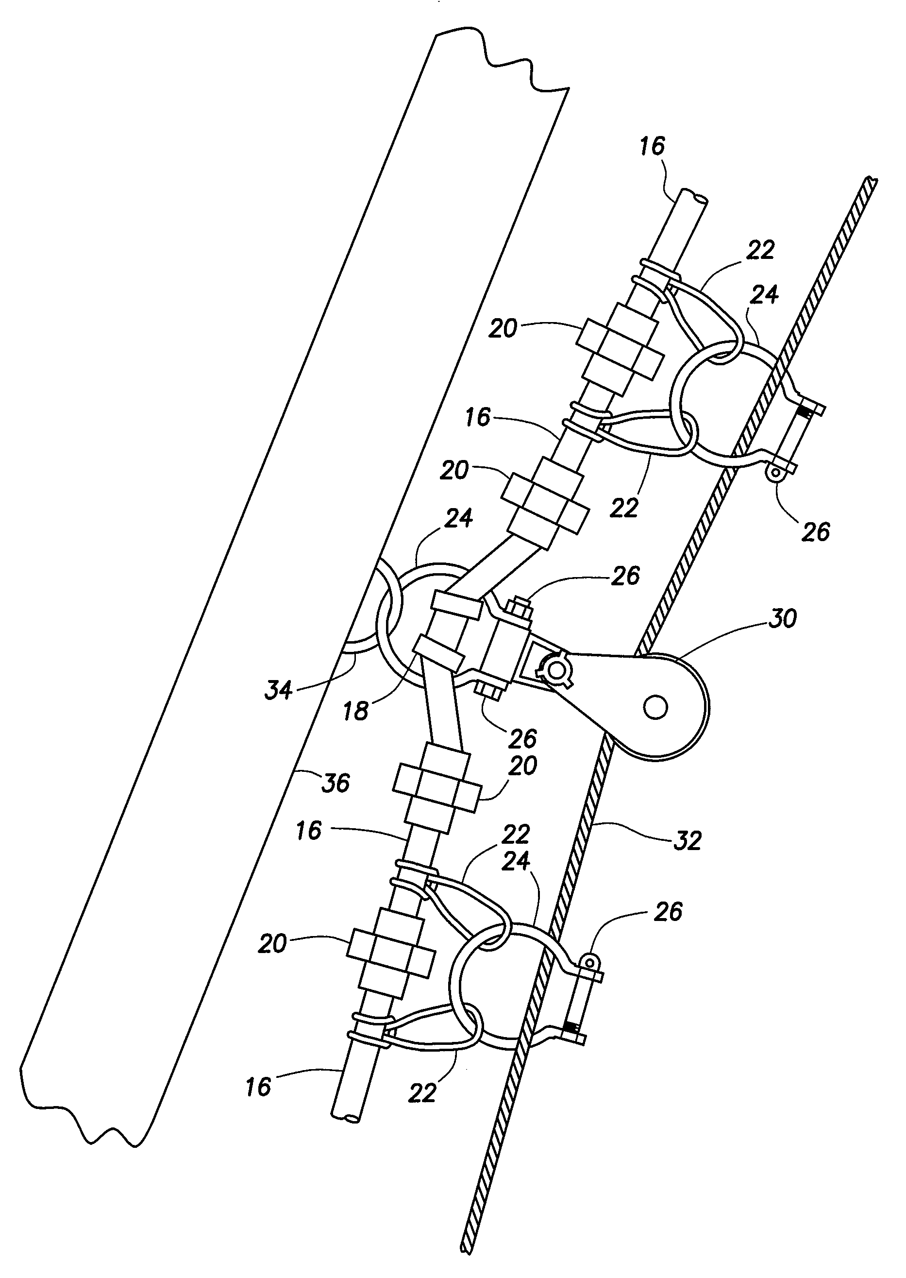
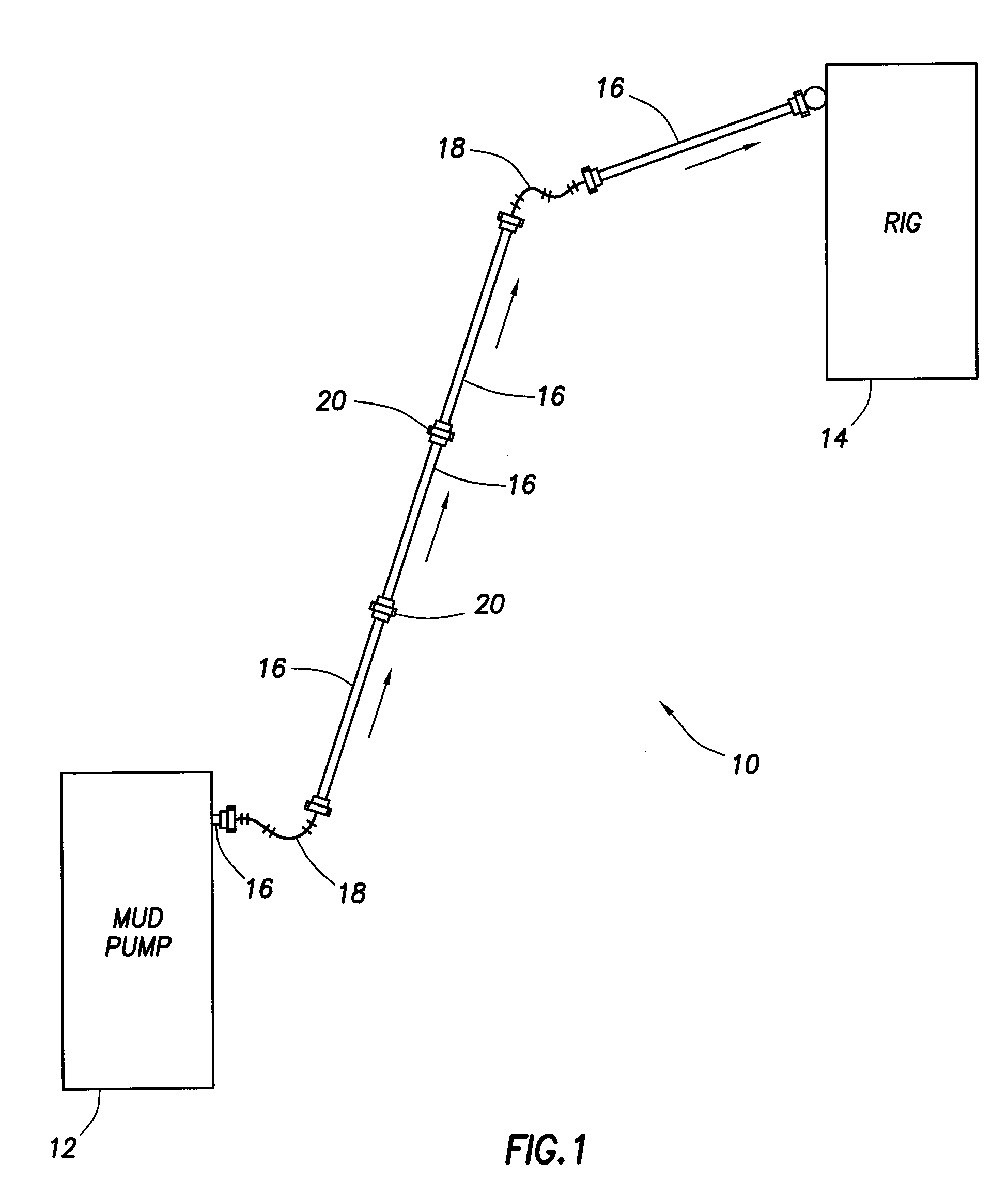
[0011]FIG. 1 is a diagram of a pump iron system, which is indicated generally at 10. Pump iron system 10 includes joints of pump iron 16 that are placed between a pump 12 and a well servicing or drilling rig 14. Drilling mud and other fluids are pumped through the pump iron system between the pump and the well servicing or drilling rig. Joints 16 are connected end to end to one by hammer unions 20. In many well servicing and drilling environments, the area between the pump and the well servicing or drilling rig is not a straight line. Instead, it is often the case that the pump iron system 10 has to be routed around obstacles at the well site. In addition, pump iron system 10 may encounter elevation changes that cause the next following joint 16 of pump iron to be higher or lower than the preceding link. In these instances, it is possible to use a swivel joint 18 to route around obstacles or to create an elevation change between successive joints in the pump iron system.
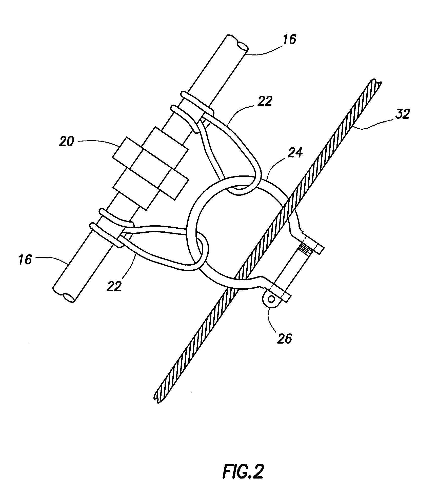
[0012]Shown ...


PUM


Abstract

A pump iron restraint system is disclosed in which a fastening system is coupled to successive pump iron joints and a wireline is threaded through the fastening system. The fastening system may comprise a pair of endless flat straps, each of which is coupled to one of the pump iron joints. The eyes of the endless flat straps are placed around the interior arch of the screw pin shackle. A wireline is placed through the spaced formed by the screw pin and the screw pin shackle. The wireline is secured at the well site so that the wireline is taut.

Description

TECHNICAL FIELD[0001]The present disclosure relates generally to the field of oilfield services and oilfield well servicing, drilling, and, more particularly, to a pump iron restraint system.BACKGROUND[0002]During a well servicing or drilling operation, pump iron is used to transport gas and / or fluid from a mud pump to the well. The pump iron is typically laid along the ground between the mud pump and the well. The pump iron is typically not laid in a straight line between the mud pump and the well. In some cases, the pump iron will have to be routed around obstacles at the well site. The pump iron is composed of swing joints, hammer unions, and lengths of pump iron. If a pump iron system were to fail due to some combination of system fatigue or pressure, the failure could be catastrophic in nature. If a pump iron system were to fail, the lengths of pump iron could be thrown about the well site, damaging other items and equipment and, more importantly, potentially causing personal i...

Claims


Application Information

Patent Timeline
Patent Type & Authority Applications(United States)
IPC IPC(8): F16L3/00
CPCF16L3/18Y10T137/6966
Inventor GAYAUT, GILBERT ANTHONY
Owner PENNY TECH S A R L
Why Eureka
Try Eureka