
Drive Control Device For Hybrid Vehicle

a hybrid vehicle and control device technology, applied in the direction of electric propulsion mounting, machines/engines, electric propulsion, etc., can solve the problems of reducing the torque and affecting the operation of the electric motor for running. , to achieve the effect of reducing the idling rotation speed, avoiding the blowing of the electric motor for running, and avoiding the delay of hydraulic respons

Active Publication Date: 2010-10-21
TOYOTA JIDOSHA KK
View PDF15 Cites 17 Cited by
  • Summary
  • Abstract
  • Description
  • Claims
  • Application Information

AI Technical Summary

Benefits of technology

The present invention relates to a drive control device for hybrid vehicles that reduces engine noise during idling and prevents hydraulic power transmission apparatus slip and electric motor for running blow up by avoiding oil pressure rise delay caused by sudden starting of the engine. The invention includes a hydraulic power transmission apparatus, a hydraulic control circuit, and a mechanical oil pump and electric oil pump driven by the engine and electric motor, respectively. The invention also includes a return determining means and torque restricting means to prevent slip and blow up of the hydraulic power transmission apparatus. The invention further includes an idling rotation speed lowering means to reduce engine noise during idling.

Problems solved by technology

In this device, since the electric motor for running receives a reaction force upon starting of the engine, a load of the hydraulic power transmission apparatus becomes large.
In the meantime, a discharge amount of the mechanical oil pump driven by the engine is small, so that a slip is likely to occur due to the oil pressure insufficiency of the hydraulic power transmission apparatus.
Hence, until the engine can completely perform self-supported rotation, the torque of the electric motor for running is restricted, and the electric oil pump is caused to operate to secure the oil pressure.

Method used


Image

  • Drive Control Device For Hybrid Vehicle
  • Drive Control Device For Hybrid Vehicle
  • Drive Control Device For Hybrid Vehicle

Examples


Embodiment Construction

[0083]An embodiment of the present invention will be described below in detail with reference to the drawings.

Preferred Embodiments

[0084]In the following description and the accompanying drawings, the present invention will be described in more detail with reference to exemplary embodiments.

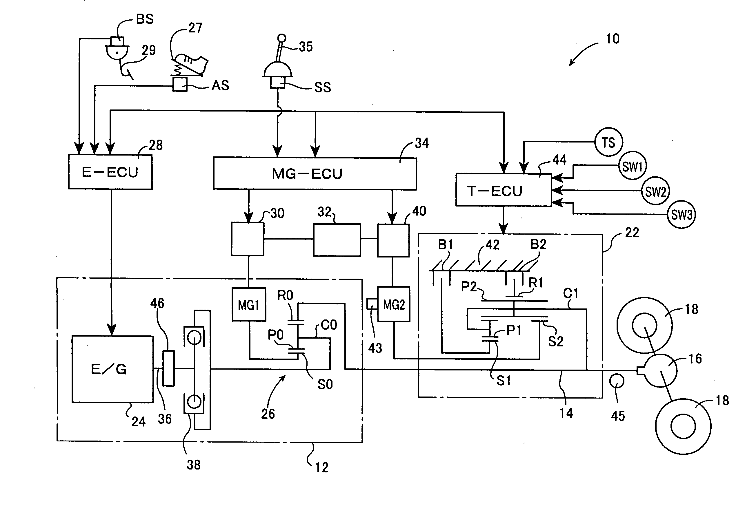
[0085]FIG. 1 is a schematic diagram illustrating a drive control device 10 to which a first embodiment as an example of the invention is applied. Referring to FIG. 1, in the drive control device 10, torque of a first drive force generation source 12 that is a main drive source is transmitted to an output shaft 14 that functions as an output member, and the torque is transmitted from the output shaft 14 to a pair of left and right driving wheels 18 via a differential gear device 16. Besides, in the drive control device 10, a second motor / generator 20 capable of selectively executing a power running control of outputting the drive power for running the vehicle and a regenerative control for recover...


PUM


Abstract

Due to the reduction of a discharge amount of a mechanical oil pump by a lowering of the idling rotation speed, a slip in a hydraulic power transmission apparatus and a blow up of an electric motor for running due to a delay of the rising of the oil pressure upon the sudden start and the like are prevented. While avoiding the slip and the blow up, the idling rotation speed is lowered so as to make the engine noise small. When the return determination from the idling state is performed based on the shift operation from P to D, at step S5, a torque TMG2 of a second motor / generator MG2 is temporarily restricted. As a result, upon the sudden start from the idling state, even when the rising of the oil pressure delays, the second brake B2 engaged upon the starting is prevented from slipping, and the second motor / generator MG2 is prevented from blowing up. As a result, while avoiding the slip of the second brake B2 and the blow up of the second motor / generator MG2 due to the hydraulic response delay, an idling rotation speed N Eidl is lowered so that the engine noise can be reduced.

Description

TECHNICAL FIELD[0001]The present invention relates to a drive control device for hybrid vehicle. In particular, the invention relates to a technology, with avoiding occurrence of a slip and the like in a hydraulic power transmission apparatus due to oil pressure insufficiency upon a sudden start and the like from an idling state, for reducing an engine noise during an idling by lowering an idling rotation speed.BACKGROUND ART[0002]As a drive control device for hybrid vehicle, those having (a) an engine used as a driving source for running and an electric motor for running, (b) a hydraulic power transmission apparatus, and (c) a hydraulic pressure control circuit, are known. The hydraulic power transmission apparatus is at least disposed in the power transmission path of the electric motor for running and transmits a power based on a torque capacity generated by an oil pressure. The hydraulic pressure control circuit includes a mechanical oil pump driven by the engine, and an electri...

Claims


Application Information

Patent Timeline
Patent Type & Authority Applications(United States)
IPC IPC(8): B60W20/00B60K6/445B60K6/54B60L15/20B60L50/16B60W10/04B60W10/06B60W10/08B60W10/10B60W10/30F02D29/00F02D29/02
CPCB60K6/445Y10T477/23B60L15/2054B60L2240/423B60L2270/142B60W10/06B60W10/08B60W20/00B60W30/18027B60W30/18054B60W2710/065B60W2710/083F02D29/02F16H59/72F16H61/0021F16H63/50F16H2037/0873F16H2061/6603F16H2312/02Y02T10/6239Y02T10/6286Y02T10/642Y02T10/7275B60L15/2009Y02T10/62Y02T10/64Y02T10/72B60W20/15B60W10/30
Inventor HAYASHI, KOJIITO, MASATOSHIKANAYAMA, TAKESHIMIKAMI, TSUYOSHI
Owner TOYOTA JIDOSHA KK
Learn More