Radiation detector comprising an imaging radiation-collimating structure

a radiation detector and imaging radiation technology, applied in the field of radiation detectors, can solve the problems of insufficient precision in manufacturing and positioning of absorbents, and achieve the effect of degrading the image quality

Inactive Publication Date: 2010-10-21
TRIXELL S
View PDF11 Cites 4 Cited by
  • Summary
  • Abstract
  • Description
  • Claims
  • Application Information

AI Technical Summary

Benefits of technology

[0006]It is an object of the invention to provide a radiation detector of the kind mentioned in the opening paragraph which is easier to manufacture than the known radiation detector and which requires a relatively low degree of precision for the positioning of the radiation absorbing elements of the imaging radiation-collimating structure without introducing visible Moiré effects in the image of an object to be imaged by the detector.

Problems solved by technology

A disadvantage of the known radiation detector is that an adequately precise manufacturing and positioning of the absorbent structure elements of the imaging radiation-collimating structure with respect to the detector elements is required.

Method used


Image

  • Radiation detector comprising an imaging radiation-collimating structure
  • Radiation detector comprising an imaging radiation-collimating structure
  • Radiation detector comprising an imaging radiation-collimating structure

Examples


Embodiment Construction

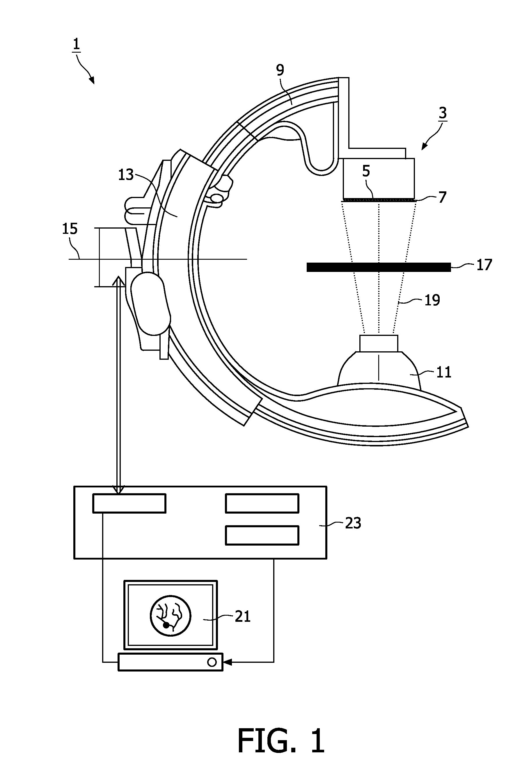
[0042]FIG. 1 schematically shows a side view of a medical X-ray examination apparatus 1 provided with a flat X-ray detector 3. The flat X-ray detector 3 is a radiation detector according to the invention and comprises a detector array 5 which is sensitive for X-rays, and a stray radiation grid 7. The X-ray examination apparatus 1 comprises a C-arm 9 from which an X-ray source 11 and the flat X-ray detector 3 are suspended. The C-arm 9 is movable through a sleeve 13 and rotatable around a horizontal axis 15. A patient table 17 is located between the X-ray source 11 and the flat X-ray detector 3. A patient to be examined (not shown) is to be positioned on the patient table 17.

[0043]To form an image of a part of the patient to be examined X-rays emanating from the X-ray source 11 propagate in straight lines 19 in the direction of the flat X-ray detector 3 thereby propagating through the patient. When propagating through the patient, a part of the X-rays is scattered, while another part...


PUM


Abstract

The invention relates to a radiation detector (3) comprising a detector array (5) having a periodical pattern of detector elements (51). Each detector element (51) comprises a sensor element (53) for converting incident radiation into an electrical charge. The sensor elements (53) are spaced at a sensor-center-to-center distance. Over the detector array (5) an imaging radiation-collimating structure (7) is disposed. The imaging radiation-collimating structure has a periodical pattern of radiation absorbing elements, which radiation absorbing elements are being spaced at a collimator center-to-center distance. The radiation detector (3) comprises a combiner for generating combiner-signals from the electrical charges of the sensor elements (53) of groups of an even number of sensor elements adjacent in a direction of the periodicity of the pattern of the radiation absorbing elements. The collimator center-to-center distance is approximately equal to twice the center-to-center distance of the groups of adjacent sensor elements. The radiation detector (3) further comprises a low-pass filter for receiving the combiner-signals and suppressing components of the combiner-signals with a frequency equal to or higher than a collimator frequency corresponding to the collimator center-to-center distance, thus providing a radiation detector which is easier to manufacture than the known radiation detector and which requires a relatively low degree of precision for the positioning of the radiation absorbing elements of the imaging radiation-collimating structure without introducing visible Moire effects in the image of an object to be imaged by the detector.

Description

FIELD OF THE INVENTION[0001]The invention relates to a radiation detector comprising[0002]a detector array having a periodical pattern of detector elements, each detector element comprising a sensor element for converting incident radiation into an electrical charge, and the sensor elements being spaced at a sensor center-to-center distance,[0003]an imaging radiation-collimating structure disposed over the detector array and having a periodical pattern of radiation absorbing elements being spaced at a collimator center-to-center distance.BACKGROUND OF THE INVENTION[0004]Such a radiation detector is known from the US patent application US2003 / 0076929. The known radiation detector comprises an array of detector elements and a stray radiation grid or a collimator of absorbent structure elements to reduce the amount of scattered radiation incident on the detector elements. The absorbent structure elements are fashioned such that their detector side center-to-center spacing in at least o...

Claims


Application Information

Patent Timeline
Patent Type & Authority Applications(United States)
IPC IPC(8): G01T1/24
CPCG21K1/00
Inventor HOORNAERT, BART PIERRE ANTOINE JOZEFWISSINK, GETTYPOORTER, TIEMEN
Owner TRIXELL S
Why Eureka
Try Eureka