Seal and Restraint System for Plastic Pipe with Low Friction Coating

Active Publication Date: 2010-10-21
S & B TECHN PRODS
View PDF10 Cites 45 Cited by
  • Summary
  • Abstract
  • Description
  • Claims
  • Application Information

AI Technical Summary

Benefits of technology

[0012]It is a further object of the invention to provide an improved seal and restraint system for plastic pipe joints utilizing a Rieber style “gasket formed” bell groove, which does not require assembly in the field and which thus simplifies installation of pipe sections at the pipe joints used to form a fluid conveying pipeline, thereby reducing the chance of human error or of damage or contamination of the gasket sealing surfaces.
[0013]Another object of the invention is to eliminate the need for an external clamping device

Problems solved by technology

Most current restraining systems offered in the industry require a substantial amount of labor to install.
Under most installation conditions, the restraining systems are cumbersome to install and represent a substantial additional effort for the contracto

Method used


Image

  • Seal and Restraint System for Plastic Pipe with Low Friction Coating
  • Seal and Restraint System for Plastic Pipe with Low Friction Coating
  • Seal and Restraint System for Plastic Pipe with Low Friction Coating

Examples


Embodiment Construction

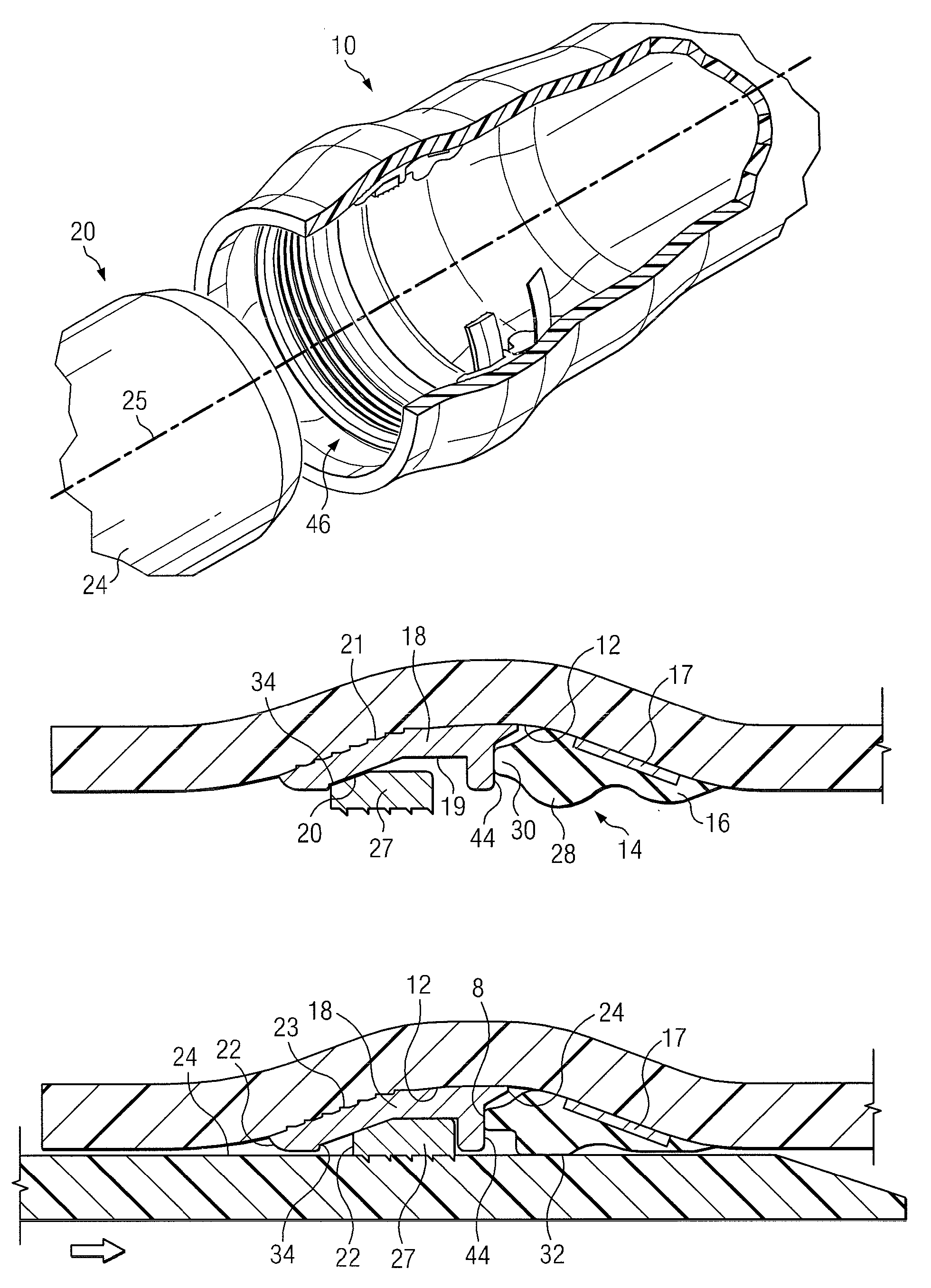
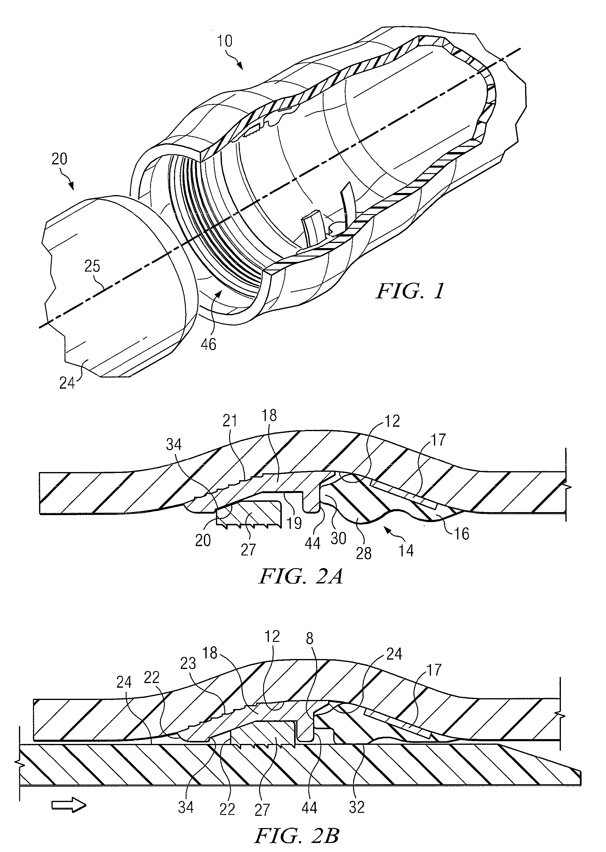
[0031]Turning to FIG. 1, there is shown an exploded view of a plastic pipe joint in which a belled female pipe end 10 is provided with an annular groove (shown as 12 in FIG. 2A) for receiving the seal and restraint mechanism 14 of the invention. The improved integral seal and restraint mechanism of the invention is capable of joining and sealing the female plastic pipe 10 to the spigot end of a mating male plastic pipe section 20 having an exterior surface 24. The plastic pipe male and female ends 10, 20 can be made from any convenient synthetic material including the polyolefins such as polyethylene and polypropylene but are preferably made from polyvinyl chloride (PVC).

[0032]As best seen in FIGS. 1, 2A and 2B, the seal and restraint mechanism 14 includes an elastomeric, circumferential sealing ring 16 which is formed as an elastomeric body. The annular sealing ring 16 is somewhat tear drop shaped in cross section and includes a bulbous end region 28 (FIG. 2A) and a thinner forward...


PUM

PropertyMeasurementUnit
Diameteraaaaaaaaaa
Corrosion propertiesaaaaaaaaaa
Heightaaaaaaaaaa

Abstract

A method and apparatus for restraining plastic pipe against both internal and external forces at a pipe or fitting connection and to join and seal at least two pipes to form a pipeline is shown featuring an improved restraining and sealing mechanism. The restraining and sealing mechanism includes a circumferential housing and a companion sealing ring which are received within a mating groove provided in the belled end of a female pipe. The circumferential housing has an interior region which contains a gripping ring insert. The sealing ring and housing are integrally located within a belled pipe end during belling operations. Either the exterior of the gripping ring or the interior of the housing is provided with a low friction coating.

Description

CROSS REFERENCE TO RELATED APPLICATIONS[0001]This application claims priority from an earlier filed provisional application Ser. No. 61 / 170,717, filed Apr. 20, 2009, entitled “Seal and Restraint System For Plastic Pipe With Low Friction Coating,” by the same inventors.BACKGROUND OF THE INVENTION[0002]1. Field of the Invention[0003]The present invention relates generally to the field of pipe connections, and in particular, to a dual function, self restraining and sealing system that is used to form a secure pipe connection between two plastic pipes and to a method of manufacturing the same.[0004]2. Description of the Related Art[0005]Pipes are commonly used for the conveyance of fluids under pressure, as in city water lines. They may also be used as free-flowing conduits running partly full, as in drains and sewers. Pipes for conveying water in appreciable quantities have been made of steel, cast iron, concrete, vitrified clay, and most recently, plastic including the various polyole...

Claims


Application Information

Patent Timeline
IPC IPC(8): F16L17/025B23P11/00B23P11/02
CPCF16L37/0925Y10T29/49826Y10T29/49865
Inventor JONES, JIMWEIH, MARK
Owner S & B TECHN PRODS
Why Eureka
Try Eureka