Mirror for the EUV wavelength range, projection objective for microlithography comprising such a mirror, and projection exposure apparatus for microlithography comprising such a projection objective

a technology of projection objective and euv light source, which is applied in the direction of lighting and heating apparatus, printers, instruments, etc., can solve the problems of reducing reflectivity, limiting the light power of euv light source, and reducing theoretical reflectivity, so as to achieve high theoretical reflectivity values

Active Publication Date: 2010-10-21
CARL ZEISS SMT GMBH
View PDF6 Cites 1 Cited by
  • Summary
  • Abstract
  • Description
  • Claims
  • Application Information

AI Technical Summary

Benefits of technology

[0008]It is an object of the invention, therefore, to provide a mirror for the EUV wavelength range, comprising sili

Problems solved by technology

Projection exposure apparatuses for microlithography for the EUV wavelength range have to rely on the fact that the mirrors utilized for the exposure or for the imaging of a mask into an image plane have a high reflectivity since, firstly, the product of the reflectivity values of the individual mirrors determines the total transmission of the projection exposure apparatus and since, secondly, E

Method used


Image

  • Mirror for the EUV wavelength range, projection objective for microlithography comprising such a mirror, and projection exposure apparatus for microlithography comprising such a projection objective
  • Mirror for the EUV wavelength range, projection objective for microlithography comprising such a mirror, and projection exposure apparatus for microlithography comprising such a projection objective
  • Mirror for the EUV wavelength range, projection objective for microlithography comprising such a mirror, and projection exposure apparatus for microlithography comprising such a projection objective

Examples


Embodiment Construction

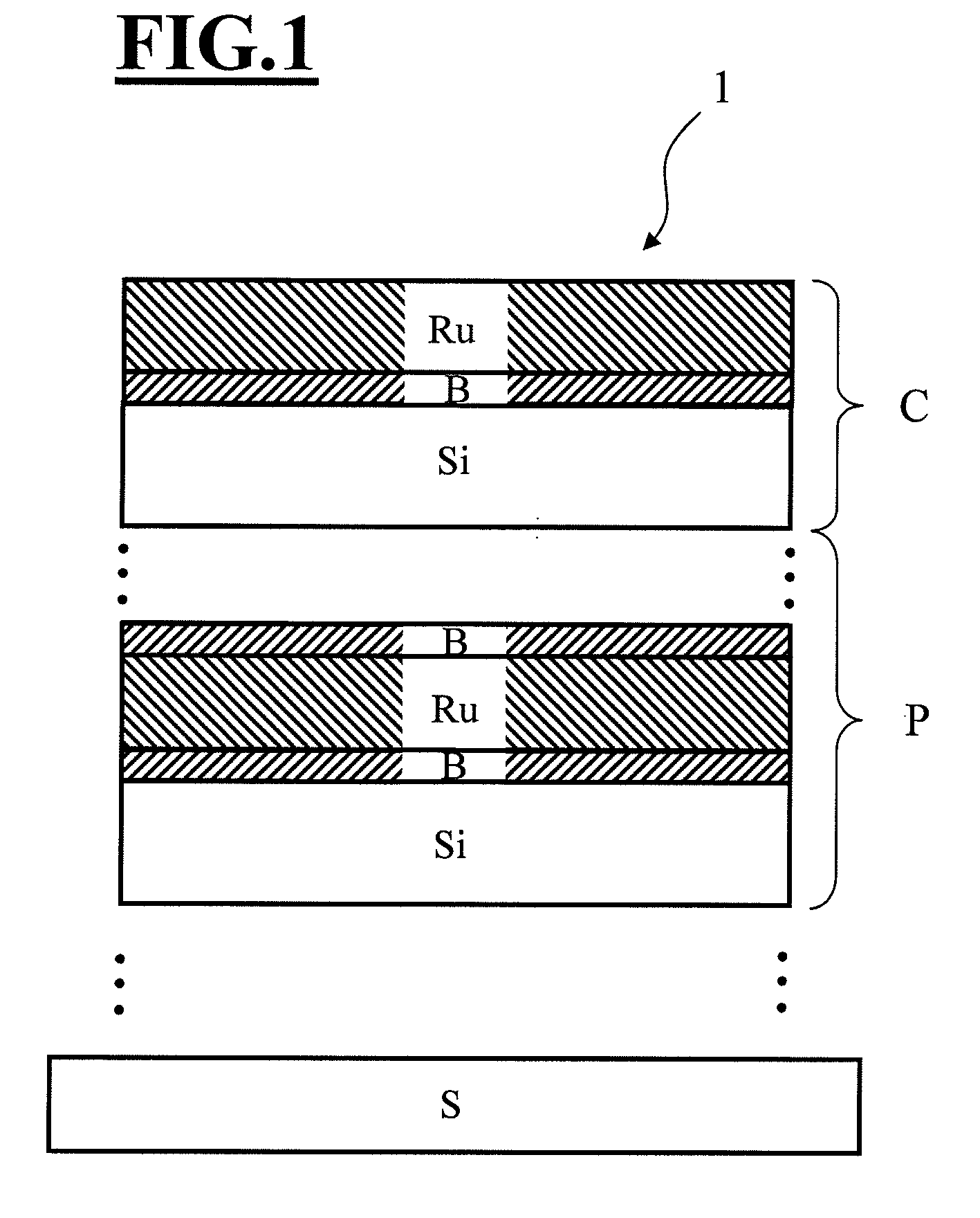
[0028]FIG. 1 shows a schematic illustration of a mirror 1 according to the invention for the EUV wavelength range having a layer arrangement P applied on a substrate S, said layer arrangement comprising a periodic sequence of individual layers, wherein the periodic sequence comprises at least two individual layers—forming a period—composed of silicon Si and ruthenium Ru, and wherein at least one barrier layer B composed of B4C having a thickness of greater than 0.35 nm, in particular greater than 0.4 nm, is situated between the individual layers composed of silicon Si and ruthenium Ru. In this case, the layer arrangement P can comprise up to 100 periods of the Ru / Si individual period illustrated. Furthermore, between the layer arrangement P and the substrate S an interlayer or an interlayer arrangement can be provided, which serves for the stress compensation of the layer arrangement. The layer arrangement P of the mirror 1 is terminated in FIG. 1 by a covering layer system C compri...


PUM


Abstract

A mirror for the EUV wavelength range (1) having a layer arrangement (P) applied on a substrate (S), the layer arrangement having a periodic sequence of individual layers, where the periodic sequence has at least two individual layers—forming a period—composed respectively of silicon (Si) and ruthenium (Ru). Also disclosed are a projection objective for microlithography (2) including such a mirror, and a projection exposure apparatus for microlithography having such a projection objective (2).

Description

[0001]The following disclosure is based on German Patent Application No. DE 10 2009 017 096.0, filed on Apr. 15, 2009, which is incorporated into the present application by reference.FIELD OF AND BACKGROUND OF THE INVENTION[0002]The invention relates to a mirror for the EUV wavelength range. Furthermore, the invention relates to a projection objective for microlithography comprising such a mirror. Moreover, the invention relates to a projection exposure apparatus for microlithography comprising such a projection objective.[0003]Projection exposure apparatuses for microlithography for the EUV wavelength range have to rely on the fact that the mirrors utilized for the exposure or for the imaging of a mask into an image plane have a high reflectivity since, firstly, the product of the reflectivity values of the individual mirrors determines the total transmission of the projection exposure apparatus and since, secondly, EUV light sources are limited in terms of their light power.[0004]...

Claims


Application Information

Patent Timeline
IPC IPC(8): G03B27/70G02B5/08
CPCG02B5/0891G03F7/70958G03F7/70316G02B17/0657
Inventor DODOC, AURELIAN
Owner CARL ZEISS SMT GMBH
Why Eureka
Try Eureka