Mechanical attachment of ceramic or metallic foam materials

a technology of ceramic or metallic foam and mechanical attachment, which is applied in the direction of machines/engines, stators, liquid fuel engines, etc., can solve the problems of oxidation, cracking, eroded ceramic coatings,

Inactive Publication Date: 2010-10-21
UNITED TECH CORP
View PDF27 Cites 19 Cited by
  • Summary
  • Abstract
  • Description
  • Claims
  • Application Information

AI Technical Summary

Problems solved by technology

Although effective, under certain thermal conditions, ceramic coatings may crack, erode, oxidize, or otherwise corrode to cause spalling.

Method used


Image

  • Mechanical attachment of ceramic or metallic foam materials
  • Mechanical attachment of ceramic or metallic foam materials
  • Mechanical attachment of ceramic or metallic foam materials

Examples


Embodiment Construction

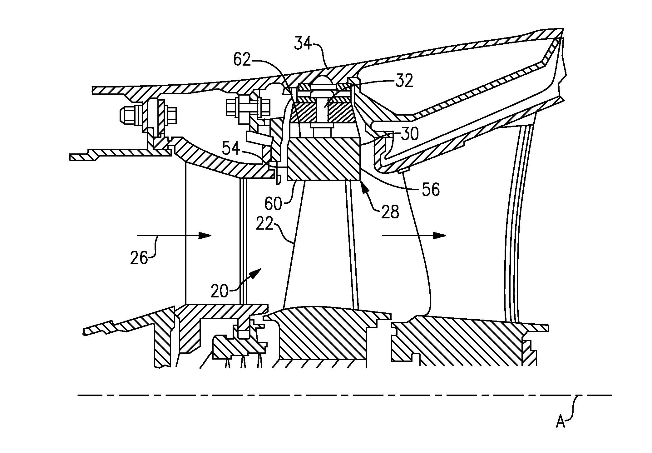
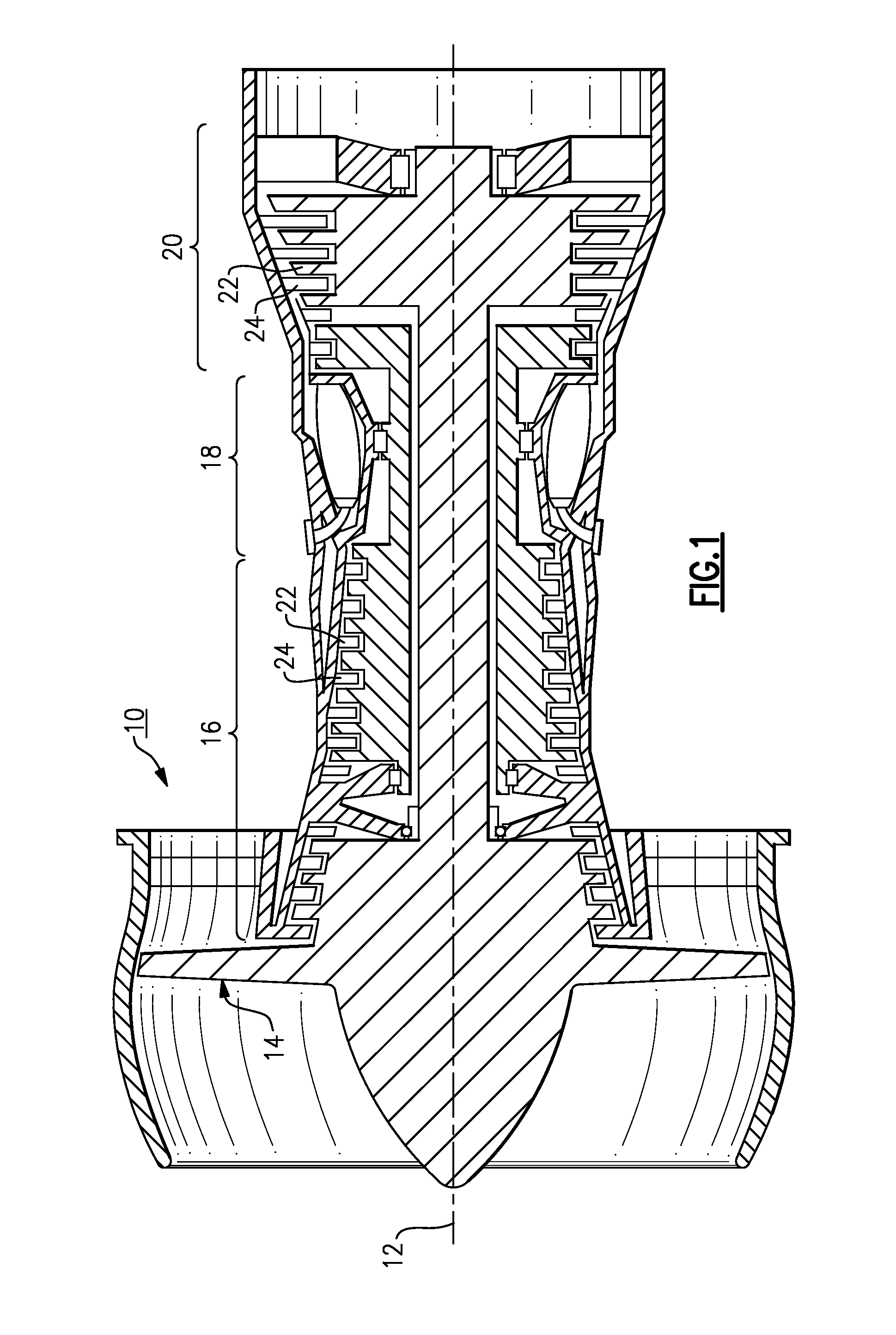
[0015]FIG. 1 illustrates selected portions of an example gas turbine engine 10, such as a gas turbine engine 10 used for propulsion. In this example, the turbine engine 10 is circumferentially disposed about an engine centerline 12 and includes a fan 14, a compressor section 16, a combustion section 18, and a turbine section 20. The combustion section 18 and the turbine section 20 include corresponding blades 22 and vanes 24. In other examples, the engine 10 may include additional engine sections or fewer engine sections than are shown in the illustrated example, depending on the type of engine and its intended use.

[0016]As is known, air compressed in the compressor section 16 is mixed with fuel and burned in the combustion section 18 to produce combustion gases that are expanded in the turbine section 20. FIG. 1 is a somewhat schematic presentation for illustrative purposes only and is not a limitation on the disclosed examples. Additionally, there are various types of gas turbine ...


PUM

PropertyMeasurementUnit
porosityaaaaaaaaaa
temperaturesaaaaaaaaaa
durabilityaaaaaaaaaa

Abstract

A thermal barrier includes a thermal barrier member having at least one material selected from a metal foam or a ceramic foam. The thermal barrier member includes an attachment section for securing the thermal barrier member with a corresponding attachment section of a support.

Description

BACKGROUND OF THE INVENTION[0001]This invention relates to thermal barriers and, more particularly, to a ceramic or metal foam thermal barrier that may be mechanically attached to a support.[0002]Components that are exposed to high temperatures, such as gas turbine engine components, typically include a protective coating system having one or more coating layers. For example, turbine blades, turbine vanes, combustor linings, and blade outer air seals may include a coating system or liner to protect from erosion, oxidation, corrosion or the like to thereby enhance durability or maintain efficient operation of the engine.[0003]Typical coating systems include a ceramic coating that is applied onto a substrate. Additional intermediate layers, such as bond coats, may be used between the ceramic coating and the substrate. Although effective, under certain thermal conditions, ceramic coatings may crack, erode, oxidize, or otherwise corrode to cause spalling.[0004]Accordingly, there is a ne...

Claims


Application Information

Patent Timeline
Patent Type & Authority Applications(United States)
IPC IPC(8): F01D11/08B32B3/06
CPCF01D11/08Y10T428/24008Y10T428/12479F05D2240/11
Inventor SCHLICHTING, KEVIN W.FRELING, MELVINDIERBERGER, JAMES A.
Owner UNITED TECH CORP
Why Eureka
Try Eureka