Vehicle gradient estimating device and vehicle traveling control device

Inactive Publication Date: 2010-10-21
HONDA MOTOR CO LTD
View PDF1 Cites 27 Cited by
  • Summary
  • Abstract
  • Description
  • Claims
  • Application Information

AI Technical Summary

Benefits of technology

[0015]With the vehicle gradient estimating device according to (1) above, the gradient of the road being traveled is estimated on the basis of the brake fluid pressure and the acceleration calculated from the traveling speed of the vehicle immediately before the vehicle stops (for example, a period before the vehicle speed is equal to or less than 2 km/h) without using an acceleration sensor for directly detecting the vehicle body acceleration. Accordingly,

Problems solved by technology

However, in the road gradient estimating device according to the related art, since the road surface gradient is estimated on the basis of the output of the acceleration sensor mounted to the vehicle, when a difference arises in a mounting angle of the acceleration sensor, there is a problem in that an estimation error of the road surface gradient increases.
In addition, even when an offset of an output increases due to a variation in timing of the acceleration sensor, there is a problem in that the estimation error of the road surface gradient increases.
In addition, since it is difficult to automatically correct the estimation error of the road surface gradient caused by the acceleration sensor when the vehicle travels or stops, there is a problem in that an inappropriate traveling control is performed due to a road surface gradient having a large estimation error.
When a downhill is estimated as a flat road, there is a problem in that a subject vehicle inappropriately moves forward to be excessively close to

Method used


Image

  • Vehicle gradient estimating device and vehicle traveling control device
  • Vehicle gradient estimating device and vehicle traveling control device
  • Vehicle gradient estimating device and vehicle traveling control device

Examples


Embodiment Construction

[0046]Hereinafter, a vehicle gradient estimating device and a vehicle traveling control device according to an embodiment of the present invention will be described with reference to the drawings.

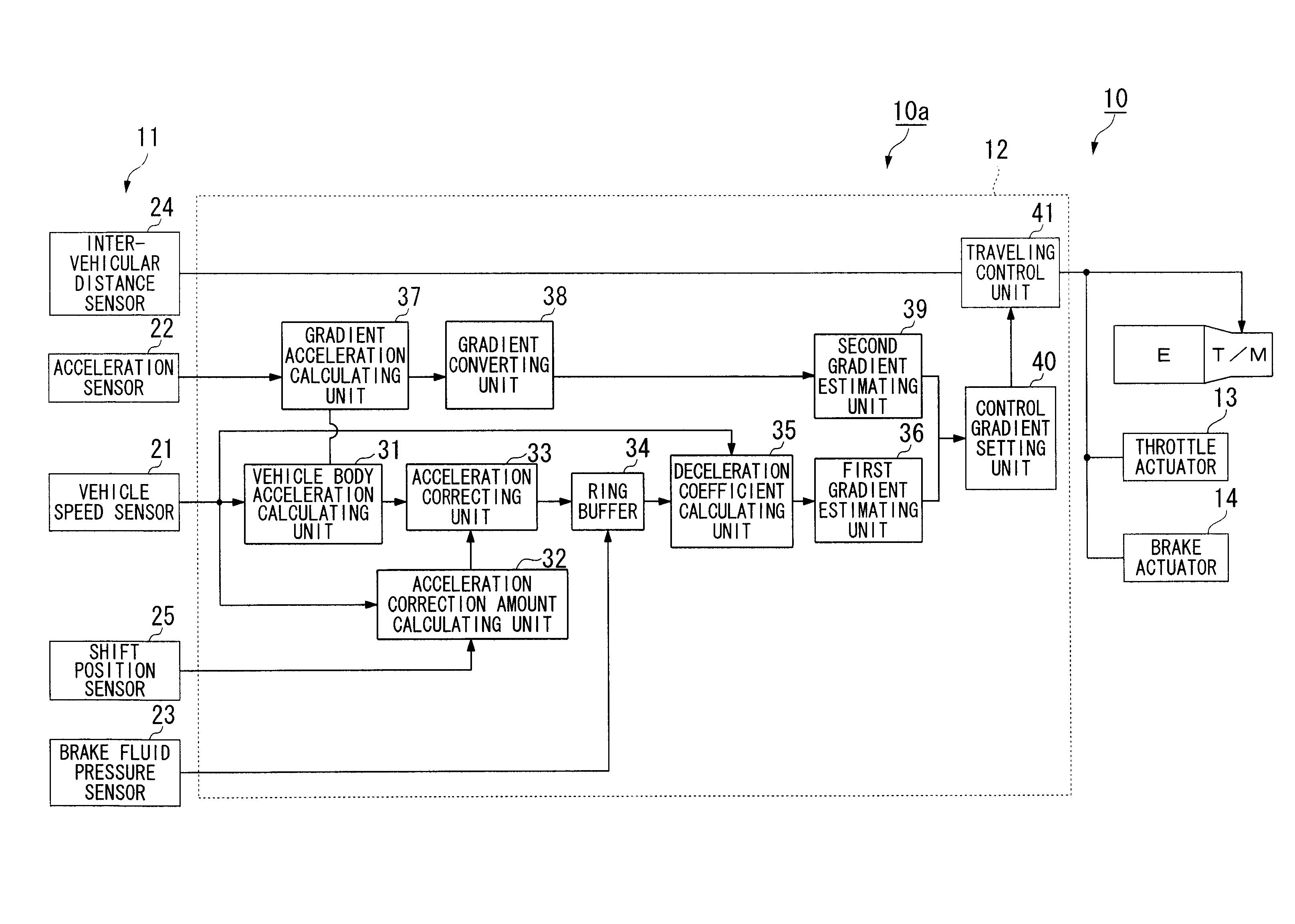
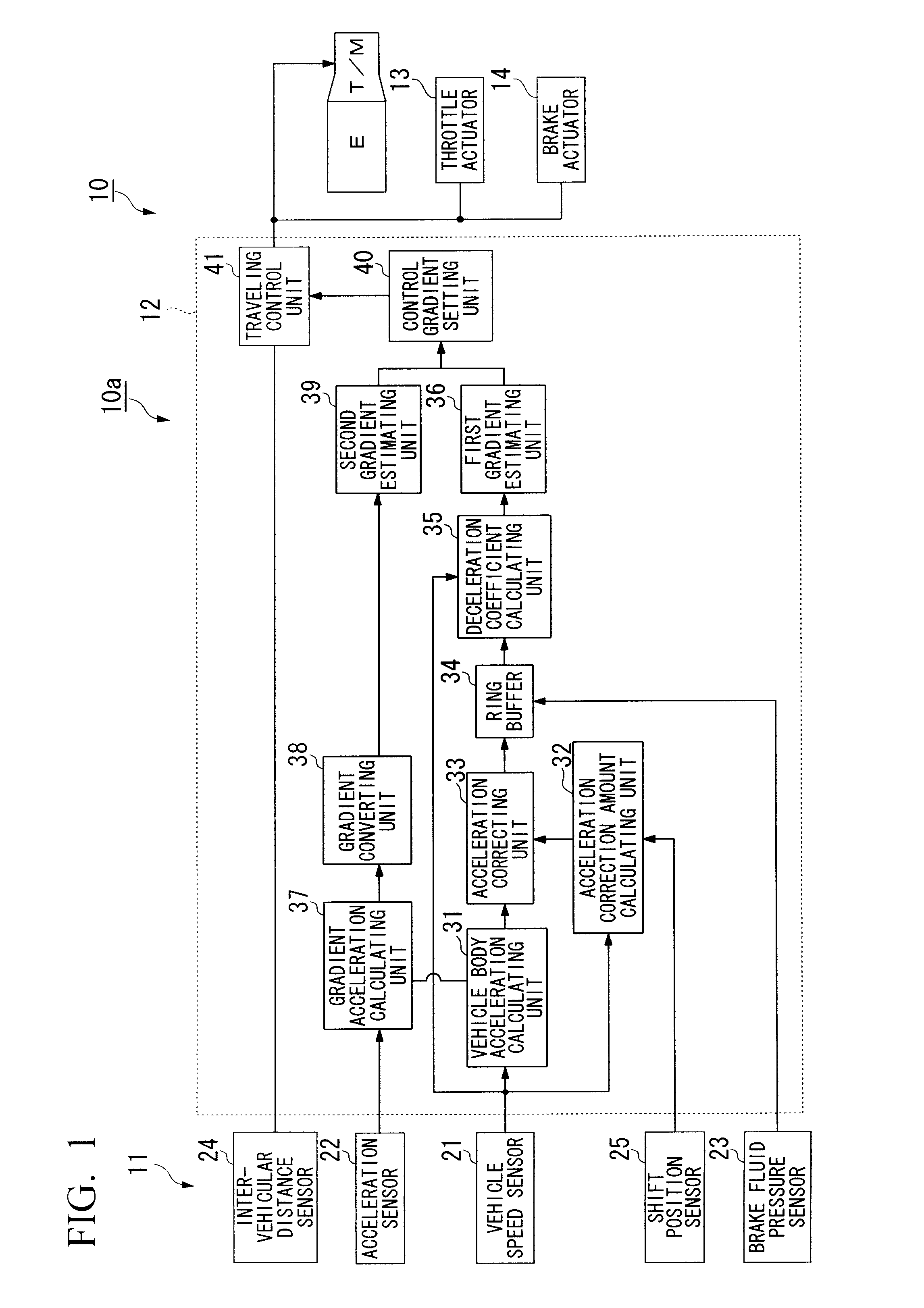
[0047]A vehicle gradient estimating device 10a according to the present embodiment is provided in a vehicle traveling control device 10. As shown in FIG. 1, the vehicle traveling control device 10 is mounted to a vehicle which transmits a driving force of an internal combustion engine (E) to a driving wheel (not shown) via a transmission (T / M), and includes a vehicle state sensor 11, a control device 12, a throttle actuator 13, and a brake actuator 14. In addition, the vehicle gradient estimating device 10a includes the vehicle state sensor 11 and the control device 12.

[0048]The vehicle state sensor 11 includes a vehicle speed sensor 21 which detects a speed (vehicle speed) of a subject vehicle, an acceleration sensor 22 which detects an acceleration acting on a vehicle body in the longitud...


PUM


Abstract

A vehicle gradient estimating device includes: a vehicle speed sensor which detects a traveling speed of a subject vehicle; an acceleration calculating unit which calculates an acceleration of the subject vehicle on the basis of the traveling speed; an engine load deceleration calculating unit which calculates a deceleration due to an engine load of the subject vehicle; an acceleration correcting unit which corrects the acceleration by using the deceleration; a brake fluid pressure detecting unit which detects a brake fluid pressure of the subject vehicle; and a first gradient estimating unit which estimates a gradient of a road being traveled of the subject vehicle, wherein the first gradient estimating unit estimates the gradient on the basis of a ratio between the brake fluid pressure and the acceleration corrected by the acceleration correcting unit.

Description

[0001]Priority is claimed on Japanese Patent Application No. 2009-103075, filed on Apr. 21, 2009, the contents of which are incorporated herein by reference.BACKGROUND OF THE INVENTION[0002]1. Field of the Invention[0003]The present invention relates to a vehicle gradient estimating device and a vehicle traveling control device.[0004]2. Description of the Related Art[0005]Heretofore, there has been known a road gradient estimating device including an acceleration sensor for detecting an acceleration acting on a vehicle in the horizontal direction and an actual acceleration sensor for calculating an acceleration from a variation in the speed of a vehicle, and estimating a road surface gradient of a road being traveled on the basis of a difference between an output of the actual acceleration sensor and an output of the acceleration sensor reflecting an acceleration of gravity due to the road surface gradient of the road being traveled (for example, refer to Japanese Unexamined Patent ...

Claims


Application Information

Patent Timeline
IPC IPC(8): G06F7/00B60T7/12B60T8/172B60W40/06B60W40/072B60W40/076
CPCB60T8/172B60W10/06B60W10/184B60W30/16B60W40/072B60W2550/142B60W2510/0657B60W2520/10B60W2520/105B60W2540/12B60W40/076B60W2552/15
Inventor ARAI, TOSHIAKISATO, HIROSHI
Owner HONDA MOTOR CO LTD
Why Eureka
Try Eureka