Gas check with system for improved loading and retention in bore of muzzleloading firearms

a technology for gas check and muzzleloading firearms, which is applied in the field of gas check with system for muzzleloading firearms, can solve the problems of significant reduction in the efficiency of such firearms, destructive interactions between bullets and bores, and malformed when being placed, so as to reduce the total surface area in contact, facilitate the loading of muzzleloading projectiles, and minimize resistance.

Active Publication Date: 2010-10-28
ACCURA BULLETAB
View PDF21 Cites 3 Cited by
  • Summary
  • Abstract
  • Description
  • Claims
  • Application Information

AI Technical Summary

Benefits of technology

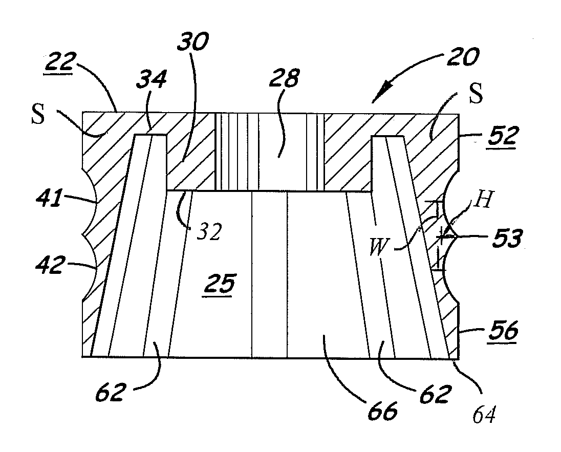
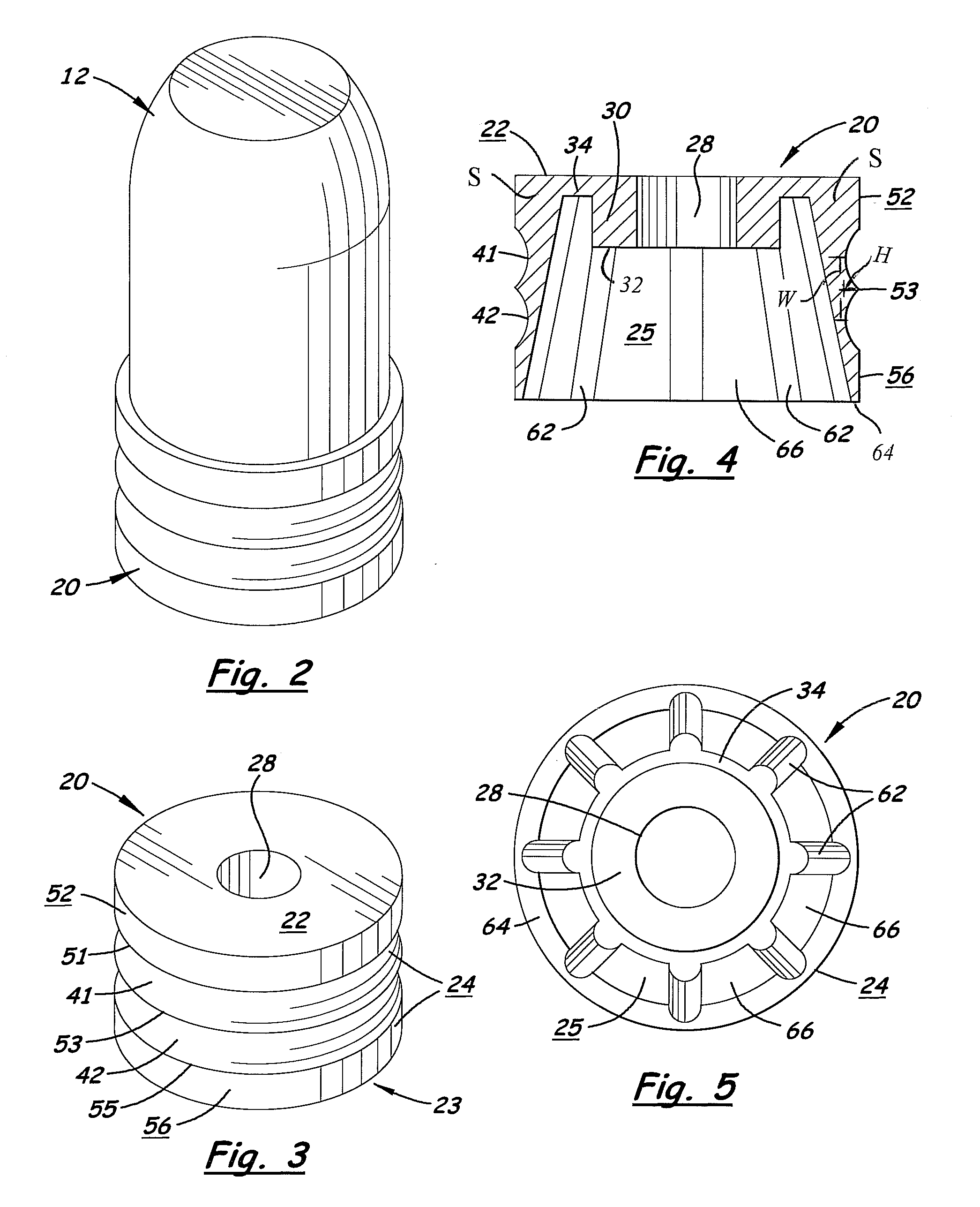
[0017]The external radial recess and ridge system of the preferred embodiments assists in convenient loading of the muzzle loading projectile, by minimizing resistance to the gas check being pushed into the barrel. This benefit is achieved by means of the external radial ridge(s) extending beyond the surrounding / adjacent portions of the external surface of the gas check for contacting the bore, with the adjacent portions of the external surface being concave or recessed relative to the ridge(s). This ridge and recess system, therefore, provide(s) less total surface area in contact with the rifle bore at all times, compared to a smooth surface gas check. This way, there is less gas-check-on-bore friction during loading, which is especially attractive when the bore has been fouled by earlier shooting. After loading, the preferred ridges contact the barrel and hold the gas check, with its firmly- and securely-connected bullet, generally centered and stable in the barrel and unlikely to slide out of the barrel. Still, however, the gas check provides enough contact with the inside of the rifle barrel to efficiently capture exploding gases and prevent blow-by upon firing.
[0018]Preferably, said capture of gases for preventing said blow-by is accomplished by a cup-shaped gas-capture portion formed at the rear end of the gas check. The gas-capture portion, also called a “skirt,” is generally axial, and it is this skirt that also provides the external surface comprising the preferred external recess and ridge system. The interior walls of the skirt tapers to be thinner towards the rear end; this way, the gas check is flexible enough at the rear end to provide, upon firing of the firearm, a good seal in the bore.
[0019]The gas check may be made rigid and durable enough at its front end to prevent excessive deformation upon explosion of the powder charge behind the gas check; this way, the front end of the gas check is preferably prevented from collapsing or compressing to a smaller / shorter axial length. Also, due to the rigidity and durability of the front end, and the security of the preferred pin (or “post”) and aperture connection system, there is no need in most embodiments for any part of the gas check to extend forward, relative to the plane of the bullet main body rear surface, for additional connection or gas capture or control. Further, while it is preferred that the gas check disengages from the bullet, breaks apart, or otherwise frees the bullet, at about the time or soon after the bullet exits the barrel, said rigidity and durability of the front end of the gas check may be desirable as a means to prevent premature rupture or compression of the gas check during the period of time inside the barrel when the gas check is fulfilling its purpose of capturing gasses and helping to propel the bullet through and out of the barrel.

Problems solved by technology

In this manner, the bullet was frictionally secured in place over the powder charge and engaged with the rifling of the bore, but was often malformed when being so placed.
Significant reductions in the efficiency of such firearms often result from destructive interactions between the bullet and bore.
When wrappers are used to surround the bullet, the positioning of the wrapper between the bullet and bore may affect the ballistic qualities of the shot.

Method used


Image

  • Gas check with system for improved loading and retention in bore of muzzleloading firearms
  • Gas check with system for improved loading and retention in bore of muzzleloading firearms
  • Gas check with system for improved loading and retention in bore of muzzleloading firearms

Examples


Embodiment Construction

[0031]Referring to the Figures, there are depicted several, but not the only, embodiments of the present invention. In this description, “front” means more towards the open end of the firearm barrel, and the front end of the bullet and gas check are toward the open end of the barrel when the bullet and gas check combination is in the breech (or closed end) of the barrel. “Back” means more towards the butt of the firearm, and the back end of the bullet and the gas check are toward the butt of the firearm when the bullet and gas check combination is in the breach.

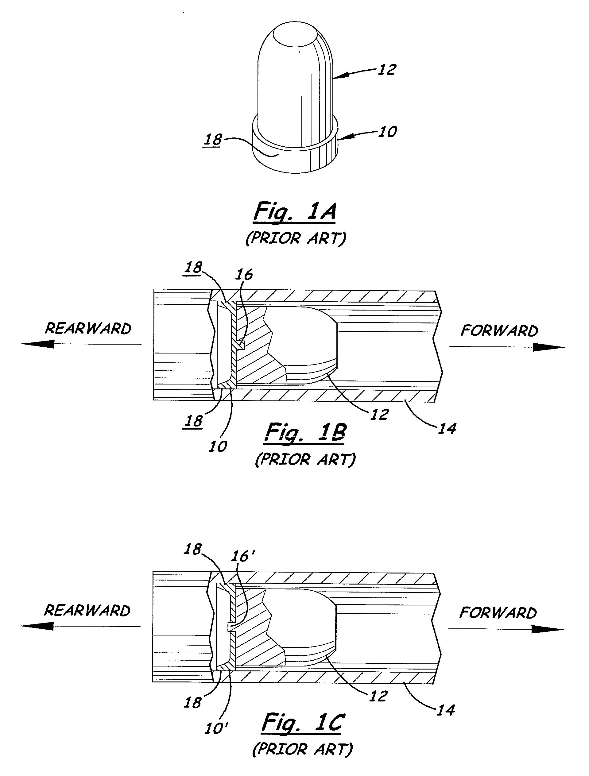
[0032]In FIG. 1A is depicted a side, perspective view of a prior art gas check attached to the back of a muzzleloading bullet. Such prior art gas checks may be of the type described by Kearns in U.S. Pat. No. 5,458,064, for example.

[0033]In FIG. 1B is depicted a cross-sectional side view of the prior art gas check 10 of FIG. 1A affixed to a muzzleloading bullet 12 within firearm barrel 14. Bullet 12 has a central hole / recess ...


PUM


Abstract

A muzzle loading bullet gas check has external recess and ridge system, and/or an internal locking ridge system. The preferred gas check has an opening or recess on its front end for receiving and frictionally engaging a rearwardly extending post of the bullet, the opening also preferably including an internal radial ridge for gripping the post and/or locking with an indent on the post. The barrel-interacting part of the gas check has one or more external recesses and adjacent radial ridges/edges protruding relative to the recesses, which serves to reduce the total surface area of the gas check contacting the bore. The recesses do not touch the bore of the firearm, resulting in less friction and easier loading, while the outer ends/surfaces of the ridges/edges do touch the bore to retain the bullet in the bore during handling and hunting and to effectively capture gasses after the firing explosion.

Description

[0001]This application claims benefit of priority of Patent Application Ser. No. 60 / 817,904, filed Jun. 30, 2006; this application is a continuation-in-part of application Ser. No. 10 / 896,160, filed Jul. 20, 2004, which is a continuation-in-part of application Ser. No. 10 / 259,374, filed Sep. 27, 2002 and issued on Jul. 20, 2004 as U.S. Pat. No. 6,763,765, which is a non-provisional of Provisional Application 60 / 325,530, filed Sep. 27, 2001; and this application is also a continuation-in-part of application Ser. No. 11 / 318,076, filed Dec. 23, 2005, the disclosures of all of which are incorporated herein by this reference.BACKGROUND OF THE INVENTION[0002]1. Field of the Invention[0003]The invention relates generally to firearms, and more specifically to muzzleloading firearms. The invention is a gas check connected to the rear part of a muzzleloader projectile, or bullet, the gas check comprising an external radial ridge for easier loading and / or a radial internal locking edge for bet...

Claims


Application Information

Patent Timeline
Patent Type & Authority Applications(United States)
IPC IPC(8): F42B14/00
CPCF42B14/06F42B14/02
Inventor HALL, DANIEL W.CROWSON, HAROLD
Owner ACCURA BULLETAB
Why Eureka
Try Eureka