Gravity-assisted drain valve for restricting intake of mildew spores

a gravity-assisted, drain valve technology, applied in water installations, thin material processing, construction, etc., can solve the problems of disadvantaged drain stoppers, backflow prevention devices drain traps that do not protect the habited environment, so as to limit the entry of unhealthy particulates

Inactive Publication Date: 2010-10-28
HOLLINGER STEVEN J
View PDF13 Cites 9 Cited by
  • Summary
  • Abstract
  • Description
  • Claims
  • Application Information

AI Technical Summary

Benefits of technology

[0016]In another aspect of the invention, the disc may include a coplanar crosshair brace with a central brace hole allowing for the through-passage of a conventional drain strainer bolt for its connection to a conventional drain crosshair in the drain; and providing structural support to the disc; and being coplanar with the lip and leaves of the disc, retaining the low-profile of the disc; and by interface with the drain strainer bolt, maintaining the leaves at exact center over the drain opening without interfering with the operation of the leaves or drain strainer bolt; and with its central brace hole conforming to the diameter of the drain strainer bolt, minimizing opportunity for the entry of odious airborne particulates into the household.
[0018]In one embodiment of the invention, the collapsing portion of the leaf is separated from opposing surfaces by a narrow gap, thereby distanced from opposing edge by the width of the gap, where the gap is of minimal width to allow the leaf to function free of entanglement or interaction with the opposing edge while continuing to perform its primary function in substantially limiting intake of airborne particulates when the leaf is in a closed position.
[0019]In another aspect of the invention, the endpoints and vertices of the gap between the leaves and opposing edges are rounded to eliminate sharp corners in order to facilitate the successful drainage of hair follicles and other particles and to provide a self-cleaning function of each leaf as it sweeps past the opposing edge.
[0021]In another aspect of the invention, the disc has a reinforced lip which enables it to be installed above and outside the drain opening while providing support to its leaf members.
[0023]In another embodiment of the invention, the disc exists at the floor of cup inserted into a conventional drain opening with the cup having a lip seated securely on the drain opening lip, so that the disc exists below the floor of the tub, rather than substantially flush with the surface of the drain opening, and so the cup collects a small volume of drainwater above the leaves and thereby acts as a trap to further limit the entry of unhealthy particulates or gases.

Problems solved by technology

A backflow prevention device does not protect the habited environment from exposure to contaminated water or unhealthy airborne particulates existing in the pipes between it and the drain opening.
The drain trap does not protect the habited environment from contaminated air existing in the area between it, the drain shoe and drain opening.
Drain stoppers are disadvantaged because they must be manually removed to allow for drainage of graywater.
While a drain strainer may alter airflow within the drain and thereby limit entry of odious particulates, the holes in a drain strainer prevent the device from substantially preventing or eliminating the entry of particulates.
Constructed of a material (i.e. rubber) that is capable of managing the forces exerted on its lower surface by projectiles within the disposal system, a disposal drain shield is poorly equipped to provide significant prevention or elimination of the passage of airborne particulates because of openings that exist at the center of the drain and between channels.
Further, because disposal drain shields are not typically employed in bathtubs, no solution for interfacing with a drain strainer bolt is provided.
The drain has a hinged door which requires significant clearance beneath the drain opening and is incapable of operating in a drain having a drain strainer bolt passing through the center of the drain.
The drain valve has a hinged door which requires significant clearance beneath the drain opening and is incapable of operating in a drain having a drain strainer bolt passing through the center of the drain.

Method used


Image

  • Gravity-assisted drain valve for restricting intake of mildew spores
  • Gravity-assisted drain valve for restricting intake of mildew spores
  • Gravity-assisted drain valve for restricting intake of mildew spores

Examples


Embodiment Construction

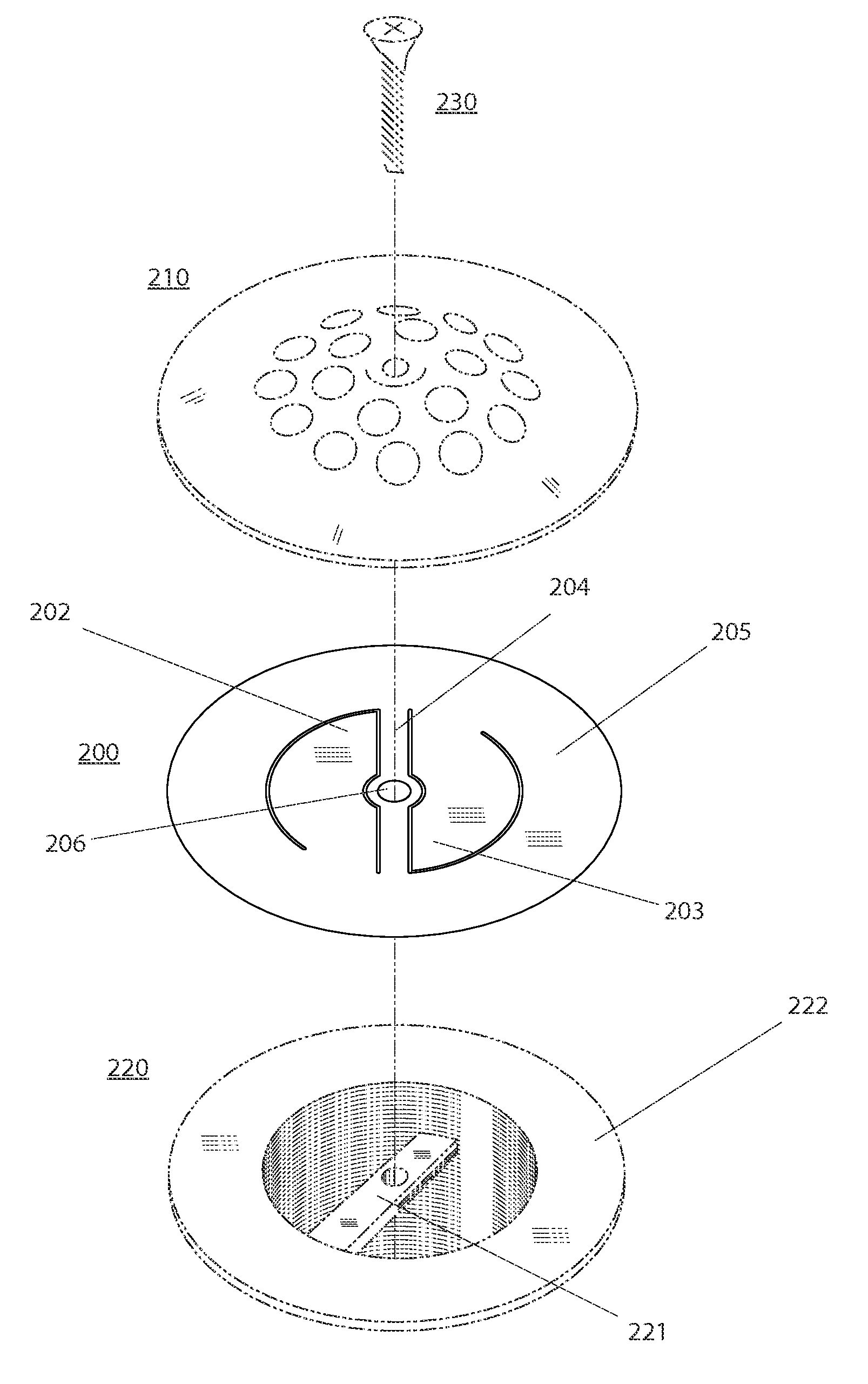
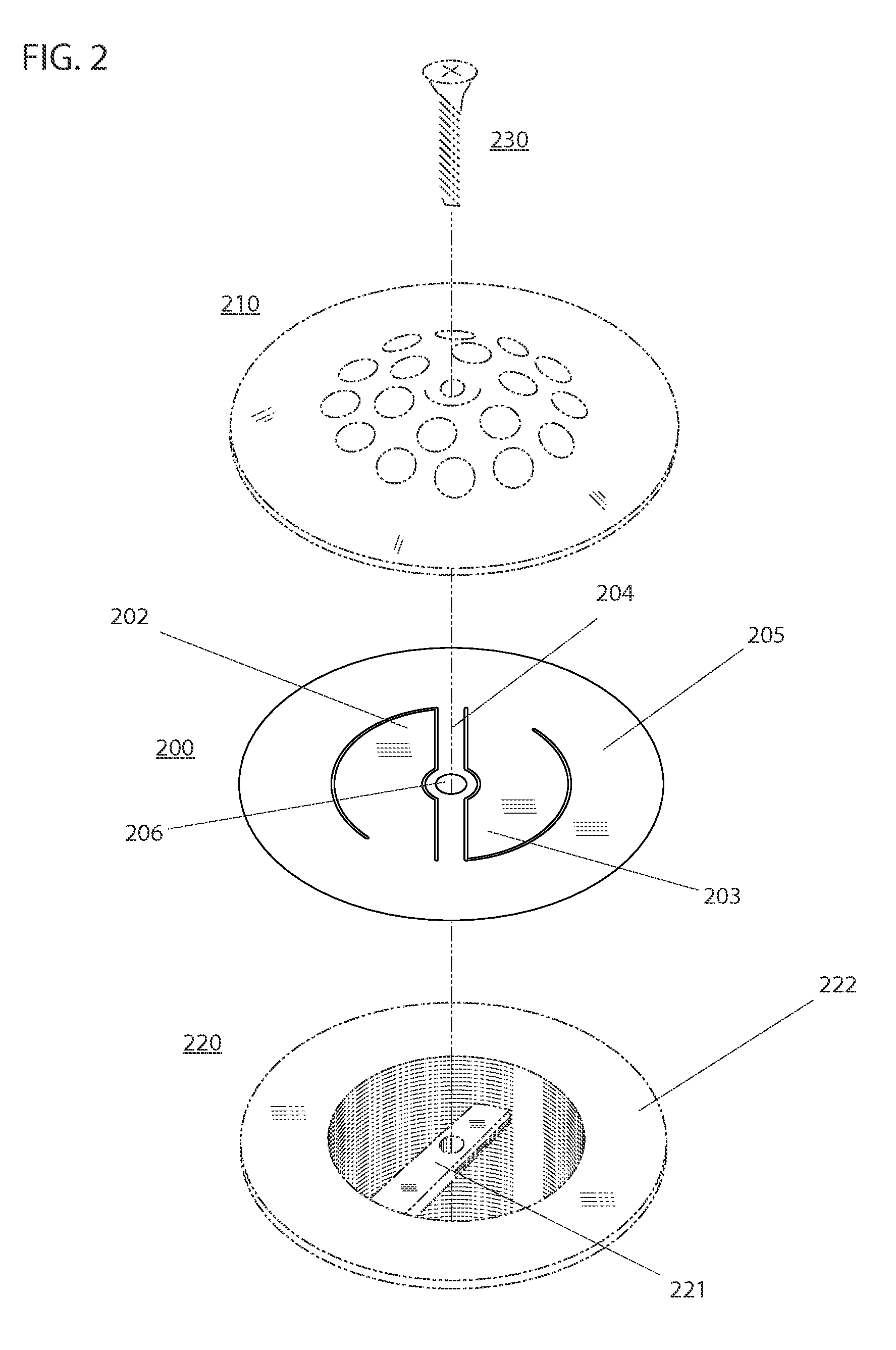
[0032]The need arises for a drain valve that limits the intake of odious particulates such as mildew spores into the habited environment while allowing for the normal drainage of fluids such as bathtub drainwater. The need further arises for such a valve that is easy to manufacture, disposable and easily replaced as a do-it-yourself project by an untrained homeowner with no plumbing experience and minimal tools. The need arises for such an intake restrictor valve to be substantially flat so as to fit beneath a conventional shower / bath drain strainer, to have a method for opening and closing that does not interfere with the drain shoe walls, the drain crosshair, the drain strainer and the centered drain strainer bolt.

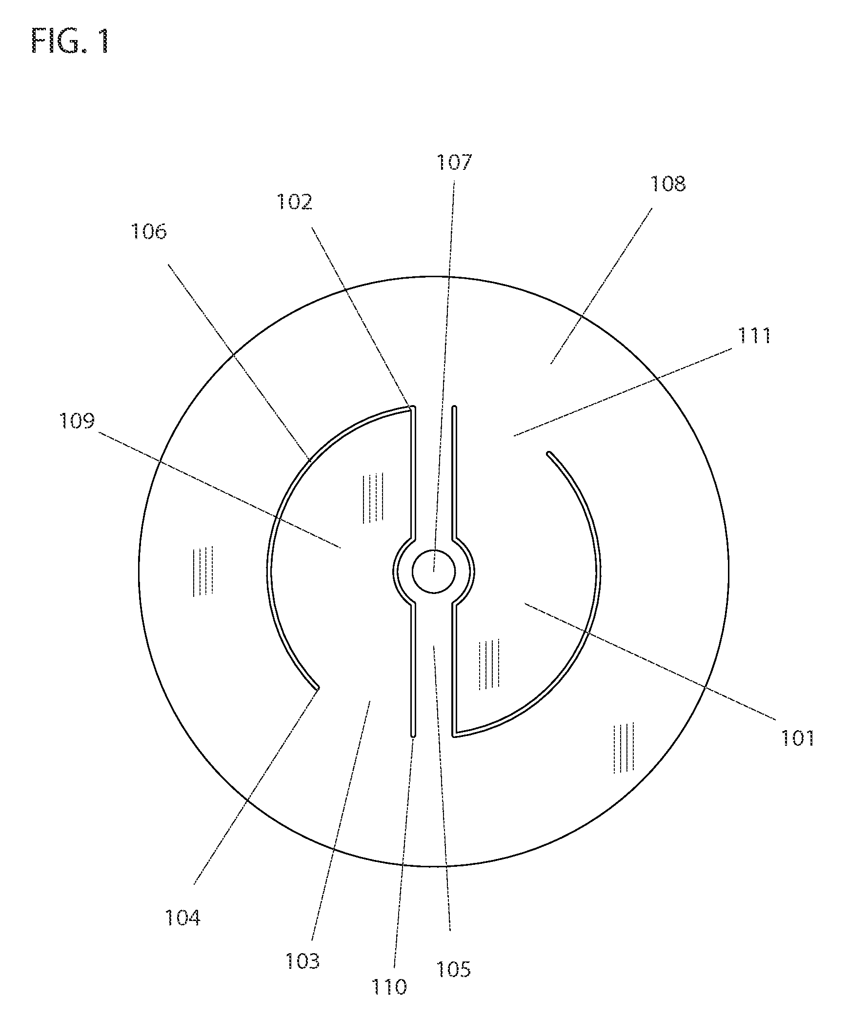
[0033]The valve of FIG. 1 is a substantially flat disc and has a Perimeter Lip that is substantially circular and encompasses the valve. The valve has two Drain Leaves 101 and 109. Brace 105 exists across the perimeter, with Brace Hole 107 at its center. Gap 106 exists b...


PUM


Abstract

A drain valve that prevents entry of odious airborne particulates into the habited environment while allowing for drainage of wastewater. The improvements include a disc with leaves cantilevered from a perimeter lip allowing the valve to operate in a drain with limited clearance between the opening and the drain crosshair below, a structural brace that effectively seals the center of the drain while allowing for through-passage of the drain strainer bolt, a gap at the perimeter edge of each leaf to prevent interference with an opposing edge, and rounded leaf edges and rounded vertices to prevent snagging of hair follicles and other draining matter. Also disclosed is a combined drain strainer and drain valve, and a drain valve installable within a drain pipe beneath the drain opening.

Description

CROSS-REFERENCE TO RELATED APPLICATIONS[0001]This application is entitled to the benefit of Provisional Patent Application Ser. No. 61 / 171,561, Gravity-assisted drain valve for restricting intake of mildew spores, filed Apr. 22, 2009, incorporated herein by reference.STATEMENT REGARDING FEDERALLY SPONSORED RESEARCH DEVELOPMENT[0002]Not applicable.BACKGROUND OF THE INVENTION[0003]1. Field of the Invention[0004]The invention has generally to do with drain valves, and more particularly a valve that limits the entry of unhealthy airborne particulates into the habited environment.[0005]2. Description of Related Art[0006]A conventional backflow prevention devices such as a backwater valves is a standard component of drainage and water storage systems to restrict the backflow of sewage water, rainwater or seawater of negative pressure from a rising water table, thus protecting the habited environment from damage, unhealthy exposure or contamination. Backflow prevention valves are installed...

Claims


Application Information

Patent Timeline
Patent Type & Authority Applications(United States)
IPC IPC(8): E03C1/10
CPCE03C1/298Y10T137/3149
Inventor HOLLINGER, STEVEN J.
Owner HOLLINGER STEVEN J
Why Eureka
Try Eureka