Drive for conveyor means or conveyed objects

a technology of conveying objects and conveyors, applied in the direction of conveying parts, conveyors, transportation and packaging, etc., can solve the problem of limited rotation of the roller body

Inactive Publication Date: 2010-10-28
WRH WALTER REIST HLDG
View PDF12 Cites 2 Cited by
  • Summary
  • Abstract
  • Description
  • Claims
  • Application Information

AI Technical Summary

Benefits of technology

[0008]It is possible thereby—in contrast to guide rollers or guide wheels, which can only allow a deflection over a circular segment—to direct and to drive the conveyed objects along (within certain limits) arbitrarily configurable curves. The central body and an orbital track of the roller body, and also a contact surface of the central body upon which the roller body rolls, can thus comprise an arbitrary course, in particular a non-circular course. The only substantial restrictions on the course are that a minimal radius of curvature must always be guaranteed, and that the torsion of the roller body is limited. With the orbital track running along a plane (as in the attached figures), no torsion of the roller body occurs. The roller body ensures a limited friction even with high normal forces, with a simultaneously simple construction: the pressure between driven means and central body is taken up by the rolling rollers, without a corresponding intrinsic heavy loading of the bearings of the axles of the rollers. This bearing simply serves to maintain the rollers apart from one another and to prevent them from falling out when in an unloaded state. The direct drive of the driven means results in an efficient transmission of power.
[0014]Preferably the drive unit is implemented as a lightweight construction, with rollers of, for example, plastic and the central body of plastic or aluminum. For heavier loads, the rollers can, in principle, also be manufactured as solid cylinders or as shells of aluminum or of (sheet) steel. In this way, a smooth-running system with limited mass inertia and with limited energy requirements is created. Since no considerable frictional forces arise—pressure is taken up by the rollers without friction on an axle—the drive unit can be operated without lubricant and is therefore less susceptible to contamination.
[0019]In a further preferred embodiment of the invention, the drive unit is furnished with an opposing unit, which lies opposite the drive unit with respect to the conveyor path in a driven section, and whose form is designed such that in a region of the driven section it corresponds to the form of the drive unit and, thus, defines a segment of the conveyor path. A concave section of the driven section corresponds thus to a convex section of the opposing unit, and vice-versa. The drive unit and the opposing unit can be elastically mounted against one another, in order to compensate for variations in the thickness of the conveyed material.

Problems solved by technology

The only substantial restrictions on the course are that a minimal radius of curvature must always be guaranteed, and that the torsion of the roller body is limited.

Method used


Image

  • Drive for conveyor means or conveyed objects
  • Drive for conveyor means or conveyed objects
  • Drive for conveyor means or conveyed objects

Examples


Embodiment Construction

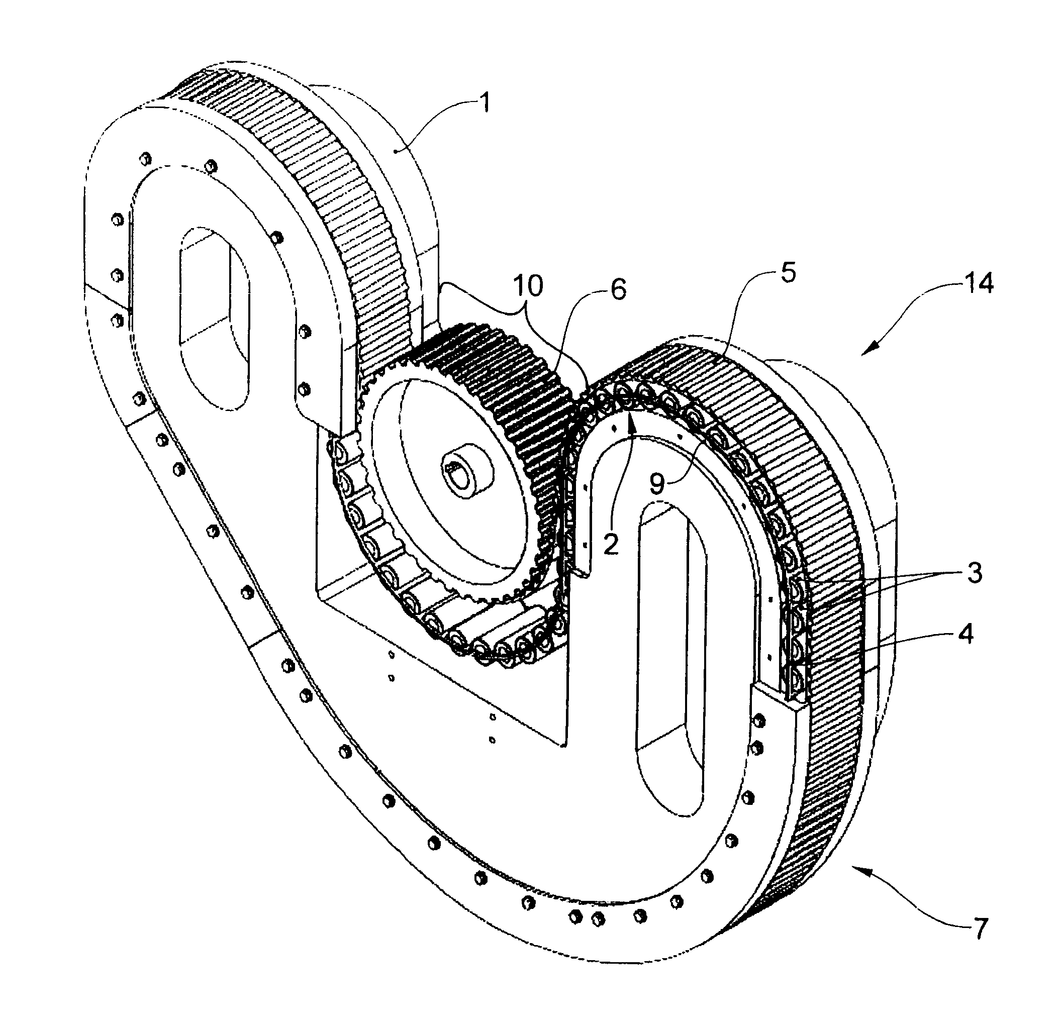
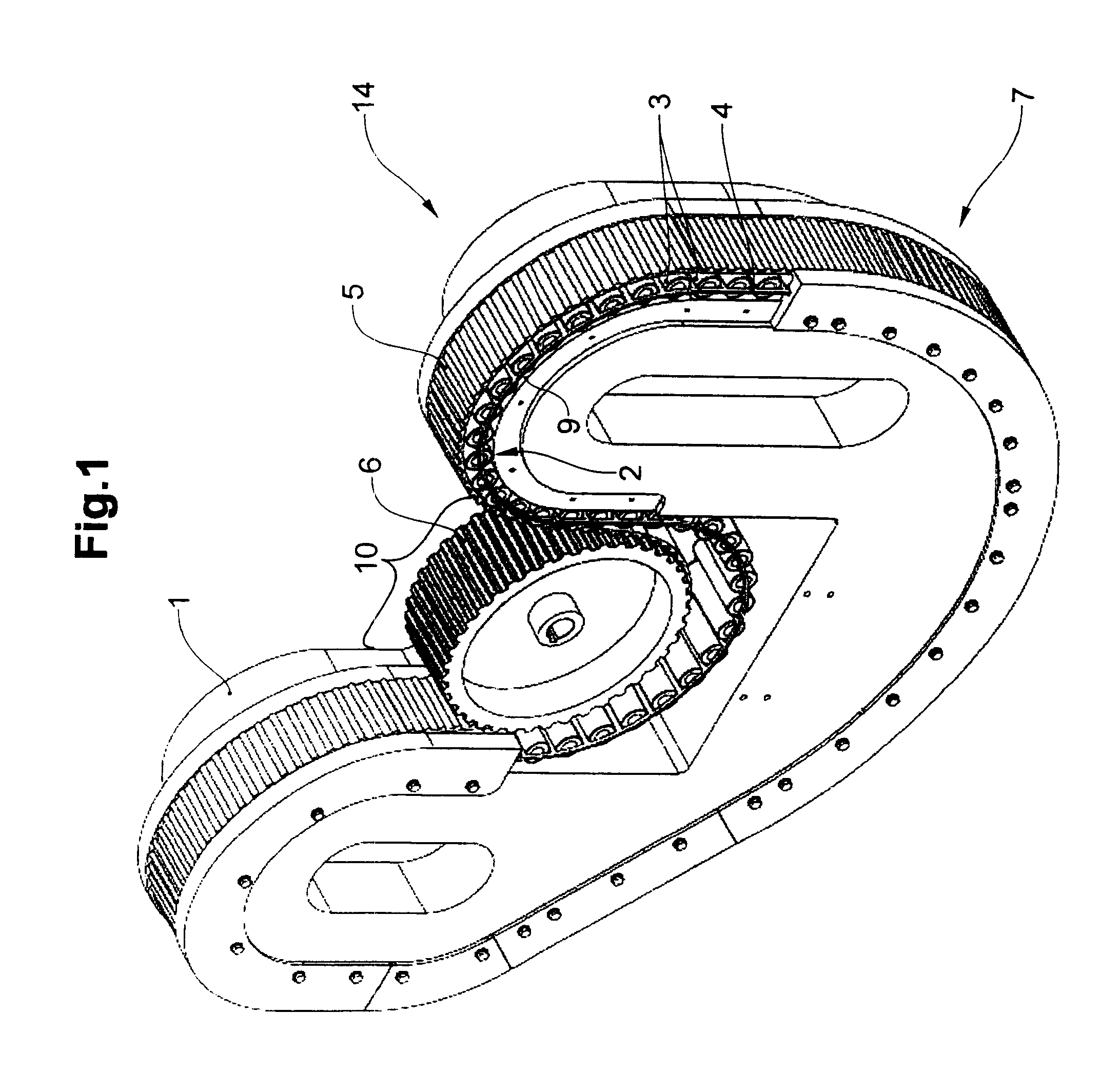
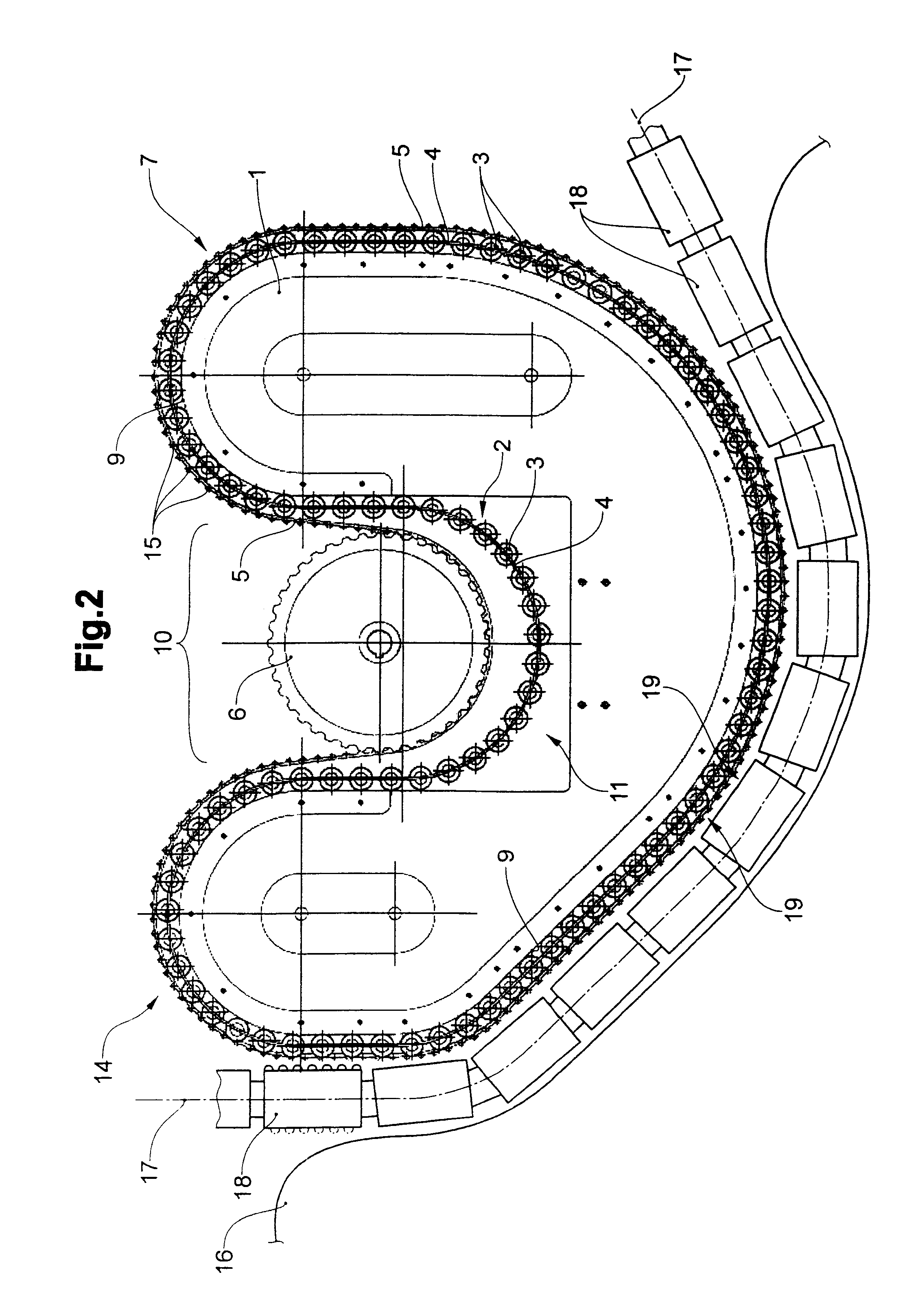
[0030]FIG. 1 depicts a perspective view of a drive unit 14, and FIG. 2 a cross section through a drive unit 14. The drive unit 14 comprises a central body 1, with a roller body 2 that runs in an orbital track 7. The roller body 2 comprises a flexible cage belt 4 with rollers 3 mounted therein. The rollers 3 roll upon a contact surface 9 of the orbital track 7. A toothed belt 5 is mounted against the roller body 2 such that it can roll thereupon. The toothed belt 5 functions as the driven element for the driving of further objects not depicted here. The toothed belt can also—differently than is shown here—be formed as a lugged belt, i.e. with lugs 15 that are spaced more substantially apart from one another, corresponding for example to a timing gap of the objects to be conveyed.

[0031]The toothed belt 5 is driven by a drive wheel, preferably a gear wheel or pinion wheel. The toothed belt 5 loops around the drive wheel 6 in a drive section 10 of the drive unit 14. For this purpose, th...


PUM


Abstract

A drive has a drive unit, wherein the drive unit includes a central body, a drive means, and a driven means circulating around the central body. Conveyor means or objects to be conveyed are able to be conveyed in a driven section of the drive unit along a conveyor path by way of the driven means. The driven means is mounted with respect to the central body by means of a roller body which circulates around the central body in an orbital track. To this end, the driven means rolls on the central body via rollers of the roller body and thereby the roller body transmits radial pressure forces to the central body. The driven means is driven directly by the drive means. The roller body itself is not driven directly by the drive means, but rather it is moved along solely by the rolling of the driven means on the roller body.

Description

BACKGROUND OF THE INVENTION[0001]1. Field of the Invention[0002]The invention relates to the field of conveying technology, in particular to a drive for conveyor means or for conveyed objects according to the preamble of claim 1.[0003]2. Description of Related Art[0004]It is known to drive conveyor belts and other conveying systems by means of toothed wheels or chains. Such drives require a deflection along an arc (wheels) and / or are burdened with high frictional losses (chains).BRIEF SUMMARY OF THE INVENTION[0005]It is therefore the object of the invention to establish a drive of the type initially described for conveying means or conveyed objects, which remedies the disadvantages described above.[0006]The drive thus comprises a drive unit, wherein the drive unit comprises a central body, a drive means, and a driven means circulating around the central body. The drive means serves for the application of driving force to the drive unit. The driven means serves for the transfer of fo...

Claims


Application Information

Patent Timeline
Patent Type & Authority Applications(United States)
IPC IPC(8): B65G23/02
CPCB65G15/28B65G39/09B65G15/60
Inventor MULLER, ERWIN
Owner WRH WALTER REIST HLDG
Why Eureka
Try Eureka