LED lamp

a technology of led lamps and diodes, which is applied in the direction of discharge tube main electrodes, semiconductor devices of light sources, lighting and heating apparatus, etc., can solve the problems of low productivity, high price and less light emission brightness of led lamps than halogen lamps, and other problems, to achieve the effect of enhancing productivity, enhancing light radiating intensity, and saving costs

Inactive Publication Date: 2010-10-28
HONG SAM PYO
View PDF2 Cites 14 Cited by
  • Summary
  • Abstract
  • Description
  • Claims
  • Application Information

AI Technical Summary

Benefits of technology

[0016]The LED lamp according to an embodiment of the present invention efficiently emits generated heats and increases intensity of light radiating toward the front portion. The lamp also has effects in enhancing productivity, saving costs, and providing elegant appearance.
[0017]The effects of the LED lamp according to the embodiments of the present invention are further explained below.
[0018]First, the front cover includes only lens hole on the surface without the ventilation opening and the fixation bolt, and thus has simple and clean design.
[0019]Second, the risk of performance deterioration caused due to ingress and accumulation of impure particles such as dust from the front is prevented, since the front cover is integrated with the lens and thus does not form a front ventilation opening.
[0020]Third, intensity of the vertical direction light is increased as loss of side horizontal-direction light radiated from the power LED is reduced, by forming a side ventilation opening in an oblique form instead of cube form, while interior is in cube form.
[0021]Fourth, as compared to conventional methods in which separate means such as adhesive is used to impregnate and fix the electrode pin and waiting time is required until the adhesive hardens, the electrode pin is mounted and soldered to the driving substrate, and the driving substrate is simply inserted into the guide installed in the interior of the socket. Accordingly, cost saving effect and simpler working process is provided.

Problems solved by technology

However, the LED lamps also have drawbacks, that is, higher price and less light emission brightness than halogen lamps.
For instance, installing a ventilation fan in the interior lamp or using the ceramic body to encourage the heat emission rate has been suggested; both have problems in high cost and low productivity.
Further, a MR 16-type LED lamp is so small that it may not provide enough space for a control board.
Thus, if the product design fails to address the above difficulty, productivity drops and the cost increases.

Method used


Image

  • LED lamp
  • LED lamp
  • LED lamp

Examples


Embodiment Construction

[0036]The preferred embodiments of the present invention are further explained below with reference to the accompanying drawings.

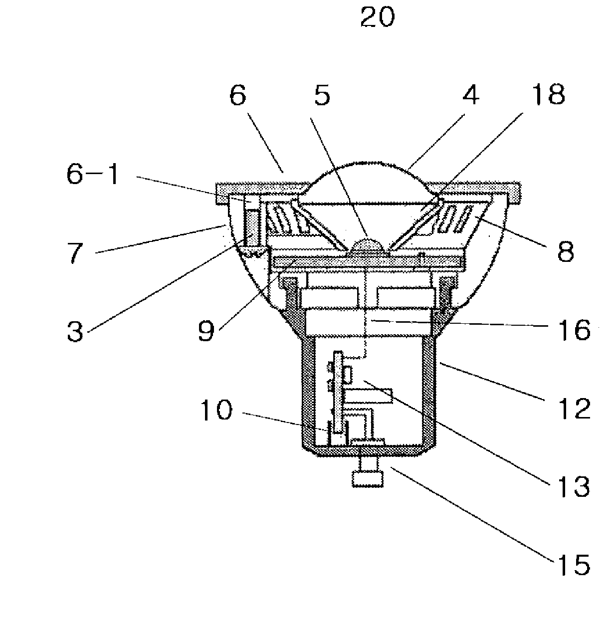
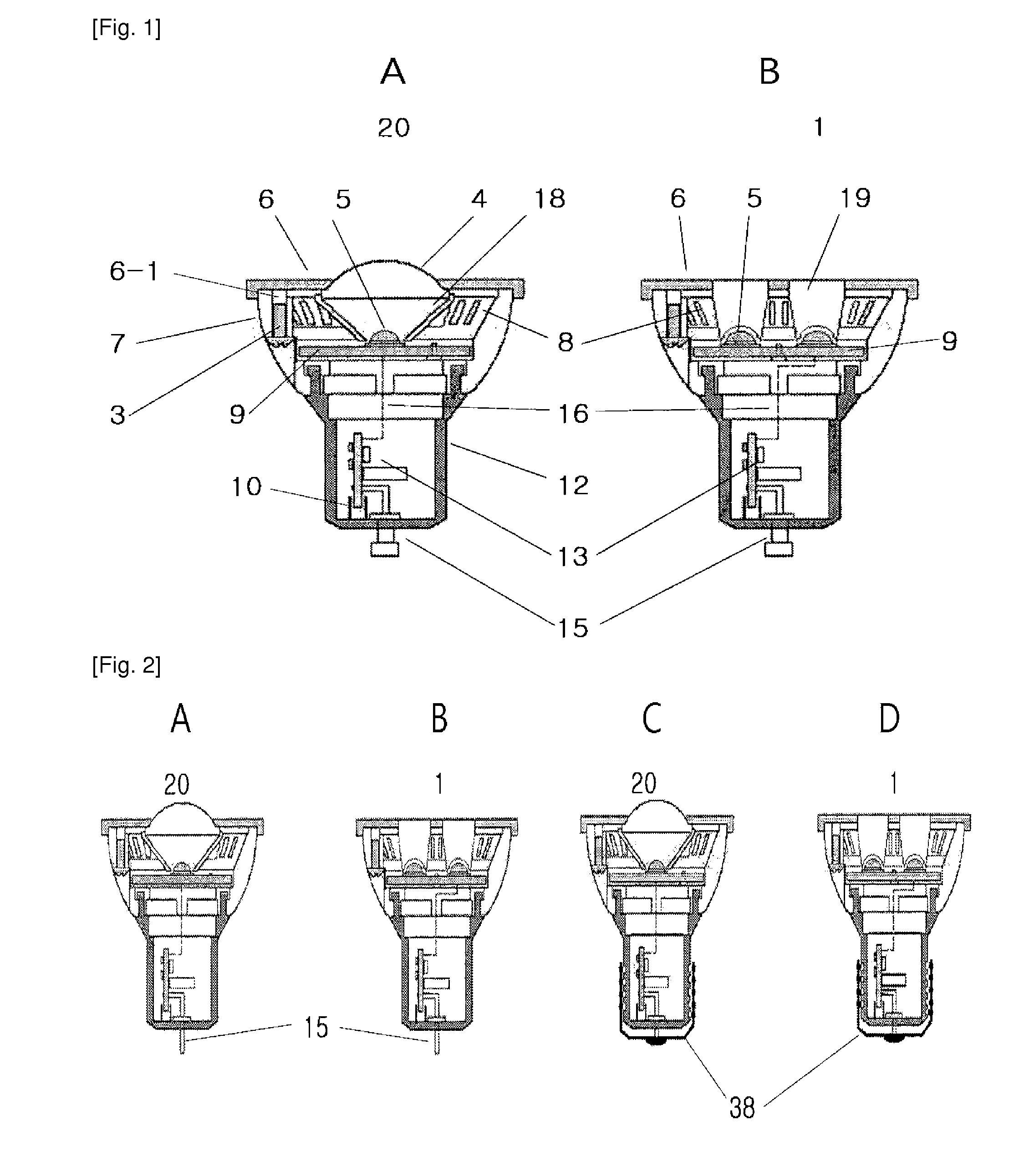
[0037]FIG. 1A is a side cross-sectional view of a LED lamp according to an embodiment of the present invention, and FIG. 1B is a side cross-sectional view of a LED lamp according to another embodiment of the present invention.

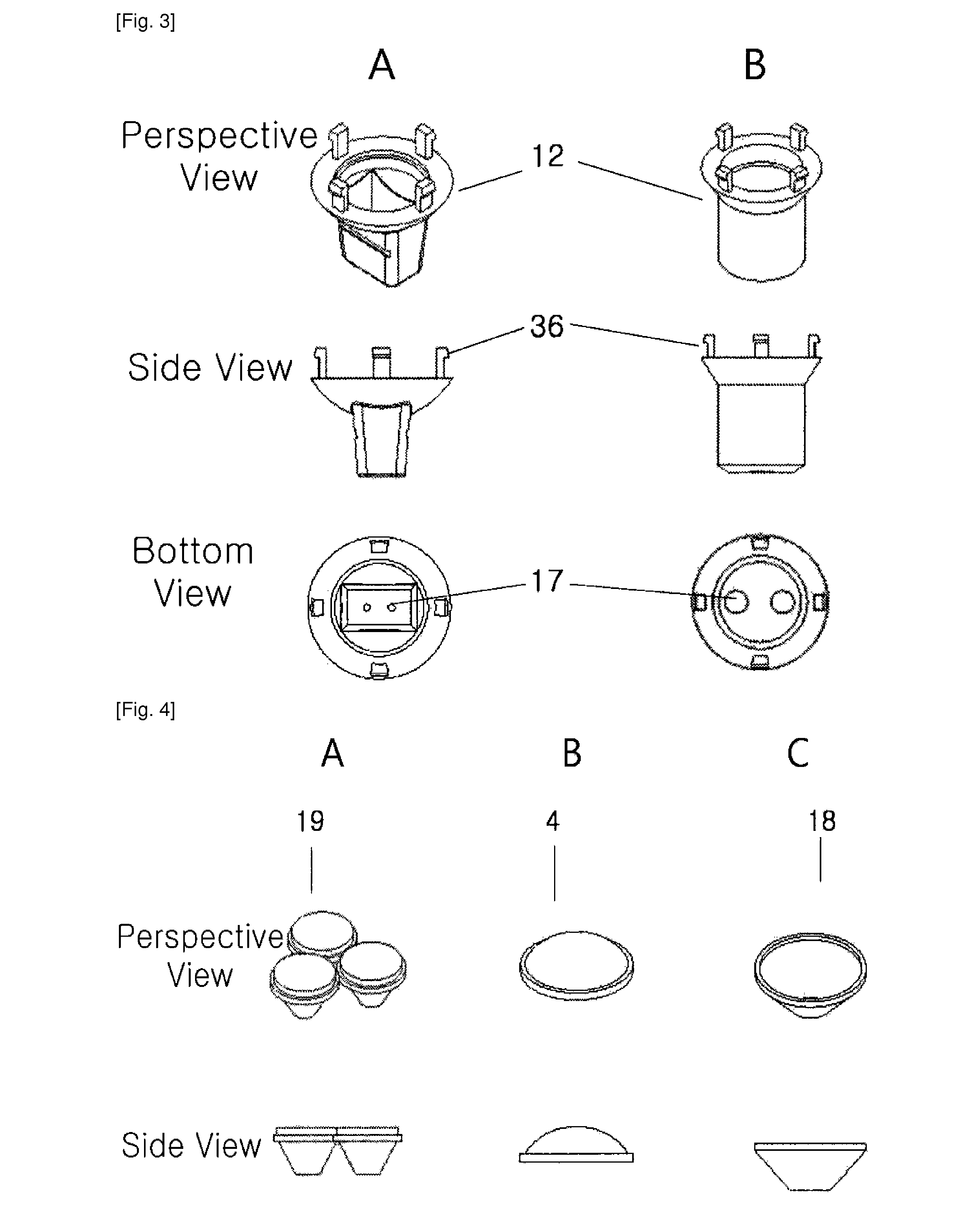
[0038]FIG. 1A shows a 1×MR16 LED lamp 20, while FIG. 1B shows a 3×MR16 LED lamp 1. FIGS. 1A and 1B are different from each other in that FIG. 1A uses a 1×LED lamp provided with a lens 4 and a lens support 18, while FIG. 1B uses a 3×LED lamp provided with a 3×lens 19.

[0039]According to FIG. 1, the LED lamp comprises a front cover 6, a body 7, and a socket 12.

[0040]The front cover 6 includes a lens hole (not drawn herein) accepting therein a lens to vertically collect light radiated from the LED; and a bolt securing portion 6-1 arranged in the back of the front cover, but excludes a front ventilation opening and a fixation bolt on the f...


PUM


Abstract

A light emitting diode (LED) lamp is provided to efficiently emit generated heat and increase light intensity radiating toward the front portion, and also to enhance productivity, save cost, and provide more elegant appearance. The LED lamp includes a front cover, a body, and a socket, in which the front cover includes a lens hole and a bolt securing portion without a front ventilation opening and a fixation bolt, the body includes a bolt securing hole, a side ventilation opening, a heat dissipation groove, a socket engagement hole, a heat conductive substrate, a lens, and a cable path, and the socket includes a driving substrate, an electrode hole, a guide and a hooking portion without adhesives in the interior portion.

Description

TECHNICAL FIELD[0001]The present invention relates to a light emitting diode (LED) lamp, and more particularly, to a LED lamp capable of solving the decline problems of heat dissipation and light radiation intensity, and enhancing output, saving cost, and providing more elegant appearance.BACKGROUND ART[0002]Conventional MR16-type LED lamps have advantages in less power consumption, lower surface temperature, and longer lifetime than halogen lamps do. However, the LED lamps also have drawbacks, that is, higher price and less light emission brightness than halogen lamps.[0003]Many attempts have been made to solve the above problems. The most critical point is to manufacture a LED lamp emitting lower heats on the surface without affecting brightness because the LED lamp lifetime itself decreases as more heat is generated. For instance, installing a ventilation fan in the interior lamp or using the ceramic body to encourage the heat emission rate has been suggested; both have problems ...

Claims


Application Information

Patent Timeline
Patent Type & Authority Applications(United States)
IPC IPC(8): H01J61/52
CPCF21Y2101/02F21V29/83F21V29/773F21K9/1375F21K9/23F21Y2115/10
Inventor HONG, SAM PYO
Owner HONG SAM PYO
Why Eureka
Try Eureka